
Chapter 8 Security in Computer Networks
8.1 What Is Network Security?
We can identify the following desirable properties of secure communication:
- Confidentiality. Only the sender and intended receiver should be able to understand the contents of the transmitted message.
- Message integrity. Alice and Bob want to ensure that the content of their communication is not altered, either maliciously or by accident, in transit.
- End-point authentication. Both the sender and receiver should be able to confirm the identity of the other party involved in the communication—to confirm that the other party is indeed who or what they claim to be.
- Operational security. Almost all organizations (companies, universities, and so on) today have networks that are attached to the public Internet. These networks therefore can potentially be compromised. Attackers can attempt to deposit worms into the hosts in the network, obtain corporate secrets, map the internal network configurations, and launch DoS attacks.
8.2 Principles of Cryptography
8.2.1 Symmetric Key Cryptography
For English text, the Caesar cipher would work by taking each letter in the plaintext message and substituting the letter that is k letters later (allowing wraparound; that is, having the letter z followed by the letter a) in the alphabet. For example if k=3, then the letter a in plaintext becomes d in ciphertext; b in plaintext becomes e in ciphertext, and so on. Here, the value of k serves as the key. As an example, the plaintext message “bob, i love you. Alice” becomes “ere, l oryh brx. dolfh” in ciphertext.

An improvement on the Caesar cipher is the monoalphabetic cipher, which also substitutes one letter of the alphabet with another letter of the alphabet. However, rather than substituting according to a regular pattern (for example, substitution with an offset of k for all letters), any letter can be substituted for any other letter, as long as each letter has a unique substitute letter, and vice versa.
A monoalphabetic cipher would also appear to be better than the Caesar cipher in that there are 26! (on the order of
Five hundred years ago, techniques improving on monoalphabetic encryption, known as polyalphabetic encryption, were invented. The idea behind polyalphabetic encryption is to use multiple monoalphabetic ciphers, with a specific monoalphabetic cipher to encode a letter in a specific position in the plaintext message. Thus, the same letter, appearing in different positions in the plaintext message, might be encoded differently. We might choose to use these two Caesar ciphers, C1 and C2, in the repeating pattern C1, C2, C2, C1, C2. The plaintext message “bob, i love you” is thus encrypted “ghu, n etox dhz”.

Block Ciphers
There are two broad classes of symmetric encryption techniques: stream ciphers and block ciphers.
In a block cipher, the message to be encrypted is processed in blocks of k bits. To encode a block, the cipher uses a one-to-one mapping to map the k-bit block of cleartext to a k-bit block of ciphertext.
Note that the number of possible mappings for a general k-block cipher is
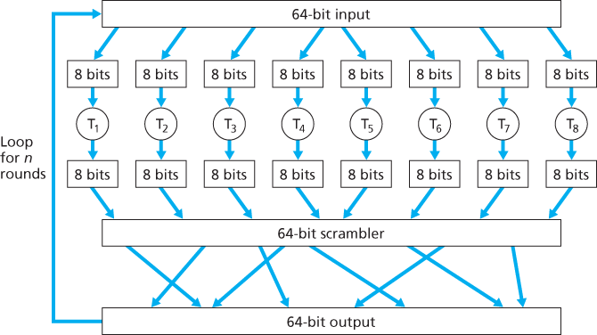
Block ciphers typically use functions that simulate randomly permuted tables. An example (adapted from [Kaufman 1995]) of such a function for bits. The function first breaks a 64-bit block into 8 chunks, with each chunk consisting of 8 bits. Each 8-bit chunk is processed by an 8-bit to 8-bit table, which is of manageable size. For example, the first chunk is processed by the table denoted by T1. Next, the 8 output chunks are reassembled into a 64-bit block. The positions of the 64 bits in the block are then scrambled (permuted) to produce a 64-bit output. This output is fed back to the 64-bit input, where another cycle begins. After n such cycles, the function provides a 64-bit block of ciphertext. The purpose of the rounds is to make each input bit affect most (if not all) of the final output bits. If only one round were used, a given input bit would affect only 8 of the 64 output bits. The key for this block cipher algorithm would be the eight permutation tables (assuming the scramble function is publicly known).
Cipher-Block Chaining
In computer networking applications, we typically need to encrypt long messages (or long streams of data). If we apply a block cipher as described by simply chopping up the message into k-bit blocks and independently encrypting each block, a subtle but important problem occurs. To see this, observe that two or more of the cleartext blocks can be identical. For example, the cleartext in two or more blocks could be “HTTP/1.1”. For these identical blocks, a block cipher would, of course, produce the same ciphertext. An attacker could potentially guess the cleartext when it sees identical ciphertext blocks and may even be able to decrypt the entire message by identifying identical ciphtertext blocks and using knowledge about the underlying protocol structure [Kaufman 1995].
To address this problem, we can mix some randomness into the ciphertext so that identical plaintext blocks produce different ciphertext blocks. To explain this idea, let
Block ciphers typically use a technique called Cipher Block Chaining (CBC). The basic idea is to send only one random value along with the very first message, and then have the sender and receiver use the computed coded blocks in place of the subsequent random number. Specifically, CBC operates as follows:
- Before encrypting the message (or the stream of data), the sender generates a random k-bit string, called the Initialization Vector (IV). Denote this initialization vector by
. The sender sends the IV to the receiver in cleartext. - For the first block, the sender calculates
that is, calculates the exclusive-or of the first block of cleartext with the IV. It then runs the result through the block-cipher algorithm to get the corresponding ciphertext block; that is, . The sender sends the encrypted block to the receiver. - For the
th block, the sender generates the th ciphertext block from .
8.2.2 Public Key Encryption
RSA
RSA makes extensive use of arithmetic operations using modulo-n arithmetic. So let’s briefly review modular arithmetic. In modular arithmetic, one performs the usual operations of addition, multiplication, and exponentiation. However, the result of each operation is replaced by the integer remainder that is left when the result is divided by n. Adding and multiplying with modular arithmetic is facilitated with the following handy facts:
It follows from the third fact that
In our discussion of RSA, let’s always keep in mind that a message is nothing but a bit pattern, and every bit pattern can be uniquely represented by an integer number (along with the length of the bit pattern). For example, suppose a message is the bit pattern 1001; this message can be represented by the decimal integer 9. Thus, when encrypting a message with RSA, it is equivalent to encrypting the unique integer number that represents the message.
There are two interrelated components of RSA:
- The choice of the public key and the private key
- The encryption and decryption algorithm
To generate the public and private RSA keys:
- Choose two large prime numbers,
and . How large should and be? The larger the values, the more difficult it is to break RSA, but the longer it takes to perform the encoding and decoding. RSA Laboratories recommends that the product of and be on the order of 1,024 bits. For a discussion of how to find large prime numbers, see [Caldwell 2012]. - Compute
and . - Choose a number,
, less than , that has no common factors (other than 1) with . (In this case, and are said to be relatively prime.) The letter is used since this value will be used in encryption. - Find a number,
, such that is exactly divisible (that is, with no remainder) by . The letter is used because this value will be used in decryption. Put another way, given , we choose such that . - The public key that Bob makes available to the world,
, is the pair of numbers ; his private key, , is the pair of numbers .
The encryption by Alice and the decryption by Bob are done as follows:
- Suppose Alice wants to send Bob a bit pattern represented by the integer number
(with ). To encode, Alice performs the exponentiation , and then computes the integer remainder when is divided by . In other words, the encrypted value, , of Alice’s plaintext message, , is . The bit pattern corresponding to this ciphertext is sent to Bob. - To decrypt the received ciphertext message,
, Bob computes .
Why Does RSA Work?
Recall that, under RSA encryption, a message (uniquely represented by an integer),
It therefore remains to show that
But remember that we have chosen
which is exactly the result we are looking for! By first exponentiating to the power of
The security of RSA relies on the fact that there are no known algorithms for quickly factoring a number, in this case the public value
8.3 Message Integrity and Digital Signatures
8.3.1 Cryptographic Hash Functions
A hash function takes an input,
- It is computationally infeasible to find any two different messages
and such that .
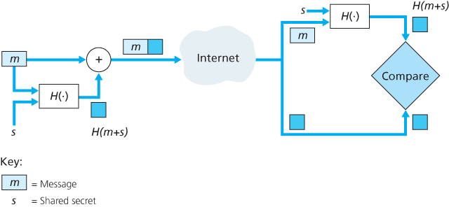
8.3.2 Message Authentication Code
To perform message integrity, in addition to using cryptographic hash functions, Alice and Bob will need a shared secret s. This shared secret, which is nothing more than a string of bits, is called the authentication key.
As you might expect, a number of different standards for MACs have been proposed over the years. The most popular standard today is HMAC, which can be used either with MD5 or SHA-1. HMAC actually runs data and the authentication key through the hash function twice [Kaufman 1995; RFC 2104].
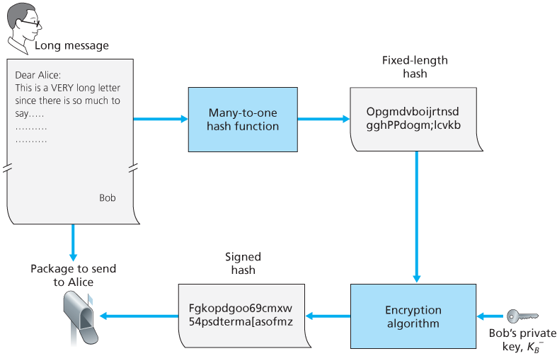
8.3.3 Digital Signatures
Public Key Certification
An important application of digital signatures is public key certification, that is, certifying that a public key belongs to a specific entity. Public key certification is used in many popular secure networking protocols, including IPsec and SSL.
Binding a public key to a particular entity is typically done by a Certification Authority (CA).
8.4 End-Point Authentication
End-point authentication is the process of one entity proving its identity to another entity over a computer network, for example, a user proving its identity to an e-mail server.
8.5 Securing E-Mail
8.5.2 PGP
Pretty Good Privacy (PGP) is a nice example of an e-mail encryption scheme [PGPI 2016]. Depending on the version, the PGP software uses MD5 or SHA for calculating the message digest; CAST, triple-DES, or IDEA for symmetric key encryption; and RSA for the public key encryption.
When PGP is installed, the software creates a public key pair for the user. The public key can be posted on the user’s Web site or placed in a public key server. The private key is protected by the use of a password. The password has to be entered every time the user accesses the private key. PGP gives the user the option of digitally signing the message, encrypting the message, or both digitally signing and encrypting.
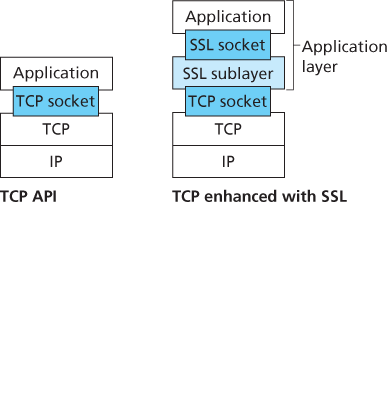
8.6 Securing TCP Connections: SSL
A slightly modified version of SSL version 3, called Transport Layer Security (TLS), has been standardized by the IETF [RFC 4346].
8.6.1 The Big Picture
Key Derivation
It is, however, generally considered safer for Alice and Bob to each use different cryptographic keys, and also to use different keys for encryption and integrity checking. Thus, both Alice and Bob use the MS to generate four keys:
= session encryption key for data sent from Bob to Alice = session MAC key for data sent from Bob to Alice = session encryption key for data sent from Alice to Bob = session MAC key for data sent from Alice to Bob
Alice and Bob each generate the four keys from the MS. This could be done by simply slicing the MS into four keys. But in real SSL it is a little more complicated. The two encryption keys will be used to encrypt data; the two MAC keys will be used to verify the integrity of the data.
Data Transfer
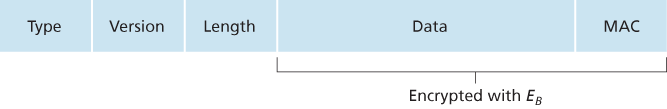
Since TCP is a byte-stream protocol, a natural approach would be for SSL to encrypt application data on the fly and then pass the encrypted data on the fly to TCP. But if we were to do this, where would we put the MAC for the integrity check? We certainly do not want to wait until the end of the TCP session to verify the integrity of all of Bob’s data that was sent over the entire session! To address this issue, SSL breaks the data stream into records, appends a MAC to each record for integrity checking, and then encrypts the record
Although this approach goes a long way, it still isn’t bullet-proof when it comes to providing data integrity for the entire message stream. In particular, suppose Trudy is a woman-in-the-middle and has the ability to insert, delete, and replace segments in the stream of TCP segments sent between Alice and Bob.
The solution to this problem, as you probably guessed, is to use sequence numbers. Bob doesn’t actually include a sequence number in the record itself, but when he calculates the MAC, he includes the sequence number in the MAC calculation.
SSL Record
8.6.2 A More Complete Picture
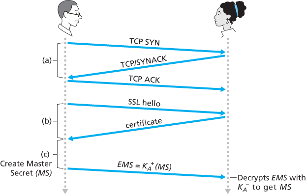
SSL Handshake
SSL does not mandate that Alice and Bob use a specific symmetric key algorithm, a specific public-key algorithm, or a specific MAC. Instead, SSL allows Alice and Bob to agree on the cryptographic algorithms at the beginning of the SSL session, during the handshake phase. Additionally, during the handshake phase, Alice and Bob send nonces to each other, which are used in the creation of the session keys (
- The client sends a list of cryptographic algorithms it supports, along with a client nonce.
- From the list, the server chooses a symmetric algorithm (for example, AES), a public key algorithm (for example, RSA with a specific key length), and a MAC algorithm. It sends back to the client its choices, as well as a certificate and a server nonce.
- The client verifies the certificate, extracts the server’s public key, generates a Pre-Master Secret (PMS), encrypts the PMS with the server’s public key, and sends the encrypted PMS to the server.
- Using the same key derivation function (as specified by the SSL standard), the client and server independently compute the Master Secret (MS) from the PMS and nonces. The MS is then sliced up to generate the two encryption and two MAC keys. Furthermore, when the chosen symmetric cipher employs CBC (such as 3DES or AES), then two Initialization Vectors (IVs)—one for each side of the connection—are also obtained from the MS. Henceforth, all messages sent between client and server are encrypted and authenticated (with the MAC).
- The client sends a MAC of all the handshake messages.
- The server sends a MAC of all the handshake messages.
8.7 Network-Layer Security: IPsec and Virtual Private Networks
The IP security protocol, more commonly known as IPsec, provides security at the network layer. IPsec secures IP datagrams between any two network-layer entities, including hosts and routers.
8.7.1 IPsec and Virtual Private Networks (VPNs)
8.7.2 The AH and ESP Protocols
IPsec is a rather complex animal—it is defined in more than a dozen RFCs. Two important RFCs are RFC 4301, which describes the overall IP security architecture, and RFC 6071, which provides an overview of the IPsec protocol suite.
In the IPsec protocol suite, there are two principal protocols: the Authentication Header (AH) protocol and the Encapsulation Security Payload (ESP) protocol. When a source IPsec entity (typically a host or a router) sends secure datagrams to a destination entity (also a host or a router), it does so with either the AH protocol or the ESP protocol. The AH protocol provides source authentication and data integrity but does not provide confidentiality. The ESP protocol provides source authentication, data integrity, and confidentiality. Because confidentiality is often critical for VPNs and other IPsec applications, the ESP protocol is much more widely used than the AH protocol.
8.7.3 Security Associations
Before sending IPsec datagrams from source entity to destination entity, the source and destination entities create a network-layer logical connection. This logical connection is called a security association (SA). An SA is a simplex logical connection; that is, it is unidirectional from source to destination. If both entities want to send secure datagrams to each other, then two SAs (that is, two logical connections) need to be established, one in each direction.
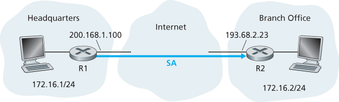
Router R1 will maintain state information about this SA, which will include:
- A 32-bit identifier for the SA, called the Security Parameter Index (SPI)
- The origin interface of the SA (in this case 200.168.1.100) and the destination interface of the SA (in this case 193.68.2.23)
- The type of encryption to be used (for example, 3DES with CBC)
- The encryption key
- The type of integrity check (for example, HMAC with MD5)
- The authentication key
Similarly, router R2 will maintain the same state information for this SA and will use this information to authenticate and decrypt any IPsec datagram that arrives from the SA.
An IPsec entity stores the state information for all of its SAs in its Security Association Database (SAD), which is a data structure in the entity’s OS kernel.
8.7.4 The IPsec Datagram
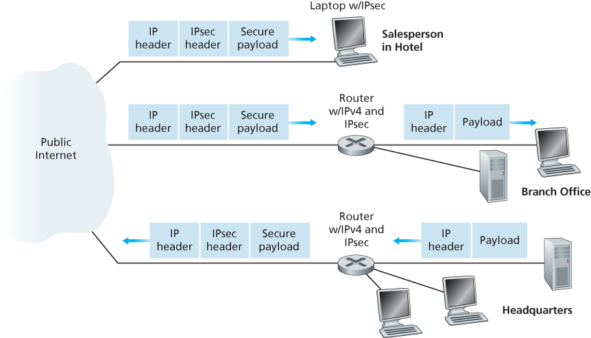
IPsec has two different packet forms, one for the so-called tunnel mode and the other for the so-called transport mode. The tunnel mode, being more appropriate for VPNs, is more widely deployed than the transport mode.
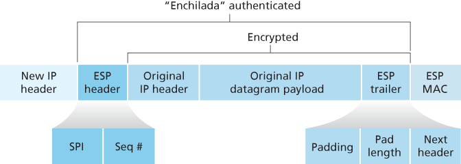
Suppose router R1 receives an ordinary IPv4 datagram from host 172.16.1.17 (in the headquarters network) which is destined to host 172.16.2.48 (in the branch-office network). Router R1 uses the following recipe to convert this “original IPv4 datagram” into an IPsec datagram:
- Appends to the back of the original IPv4 datagram (which includes the original header fields!) an “ESP trailer” field
- Encrypts the result using the algorithm and key specified by the SA
- Appends to the front of this encrypted quantity a field called “ESP header”; the resulting package is called the “enchilada”
- Creates an authentication MAC over the whole enchilada using the algorithm and key specified in the SA
- Appends the MAC to the back of the enchilada forming the payload
- Finally, creates a brand new IP header with all the classic IPv4 header fields (together normally 20 bytes long), which it appends before the payload
As you might expect, they are set to the source and destination router interfaces at the two ends of the tunnels, namely, 200.168.1.100 and 193.68.2.23. Also, the protocol number in this new IPv4 header field is not set to that of TCP, UDP, or SMTP, but instead to 50, designating that this is an IPsec datagram using the ESP protocol.
Along with a SAD, the IPsec entity also maintains another data structure called the Security Policy Database (SPD). The SPD indicates what types of datagrams (as a function of source IP address, destination IP address, and protocol type) are to be IPsec processed; and for those that are to be IPsec processed, which SA should be used.
8.7.5 IKE: Key Management in IPsec
When a VPN has a small number of end points, the network administrator can manually enter the SA information (encryption/authentication algorithms and keys, and the SPIs) into the SADs of the endpoints. Such “manual keying” is clearly impractical for a large VPN, which may consist of hundreds or even thousands of IPsec routers and hosts. Large, geographically distributed deployments require an automated mechanism for creating the SAs. IPsec does this with the Internet Key Exchange (IKE) protocol, specified in RFC 5996.
IKE has some similarities with the handshake in SSL. Each IPsec entity has a certificate, which includes the entity’s public key. As with SSL, the IKE protocol has the two entities exchange certificates, negotiate authentication and encryption algorithms, and securely exchange key material for creating session keys in the IPsec SAs. Unlike SSL, IKE employs two phases to carry out these tasks.
The first phase consists of two exchanges of message pairs between R1 and R2:
- During the first exchange of messages, the two sides use Diffie-Hellman (see Homework Problems) to create a bi-directional IKE SA between the routers. To keep us all confused, this bi-directional IKE SA is entirely different from the IPsec SAs. The IKE SA provides an authenticated and encrypted channel between the two routers. During this first message-pair exchange, keys are established for encryption and authentication for the IKE SA. Also established is a master secret that will be used to compute IPSec SA keys later in phase 2. Observe that during this first step, RSA public and private keys are not used. In particular, neither R1 nor R2 reveals its identity by signing a message with its private key.
- During the second exchange of messages, both sides reveal their identity to each other by signing their messages. However, the identities are not revealed to a passive sniffer, since the messages are sent over the secured IKE SA channel. Also during this phase, the two sides negotiate the IPsec encryption and authentication algorithms to be employed by the IPsec SAs.
In phase 2 of IKE, the two sides create an SA in each direction. At the end of phase 2, the encryption and authentication session keys are established on both sides for the two SAs. The primary motivation for having two phases in IKE is computational cost—since the second phase doesn’t involve any public-key cryptography, IKE can generate a large number of SAs between the two IPsec entities with relatively little computational cost.
8.8 Securing Wireless LANs
8.8.1 Wired Equivalent Privacy (WEP)
The IEEE 802.11 WEP protocol was designed in 1999 to provide authentication and data encryption between a host and a wireless access point (that is, base station) using a symmetric shared key approach. WEP does not specify a key management algorithm, so it is assumed that the host and wireless access point have somehow agreed on the key via an out-of-band method. Authentication is carried out as follows:
- A wireless host requests authentication by an access point.
- The access point responds to the authentication request with a 128-byte nonce value.
- The wireless host encrypts the nonce using the symmetric key that it shares with the access point.
- The access point decrypts the host-encrypted nonce.
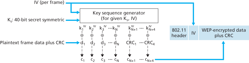
A secret 40-bit symmetric key,
The IV value changes from one frame to the next and is included in plaintext in the header of each WEP-encrypted 802.11 frame. The receiver takes the secret 40-bit symmetric key that it shares with the sender, appends the IV, and uses the resulting 64-bit key (which is identical to the key used by the sender to perform encryption) to decrypt the frame:
Proper use of the RC4 algorithm requires that the same 64-bit key value never be used more than once. Recall that the WEP key changes on a frame-by-frame basis. For a given
8.8.2 IEEE 802.11i
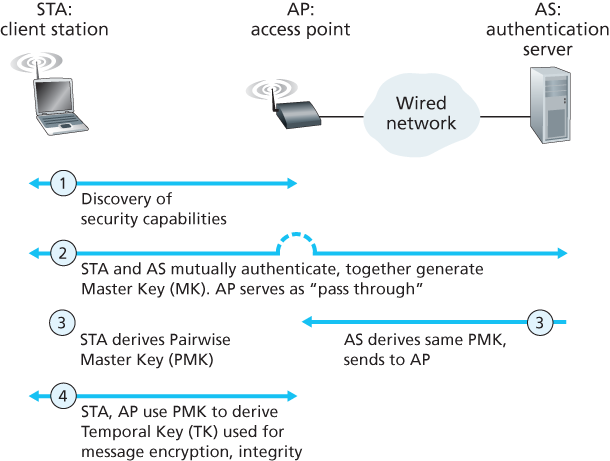
802.11i operates in four phases:
- Discovery. In the discovery phase, the AP advertises its presence and the forms of authentication and encryption that can be provided to the wireless client node. The client then requests the specific forms of authentication and encryption that it desires. Although the client and AP are already exchanging messages, the client has not yet been authenticated nor does it have an encryption key, and so several more steps will be required before the client can communicate with an arbitrary remote host over the wireless channel.
- Mutual authentication and Master Key (MK) generation. Authentication takes place between the wireless client and the authentication server. In this phase, the access point acts essentially as a relay, forwarding messages between the client and the authentication server. The Extensible Authentication Protocol (EAP) [RFC 3748] defines the end-to-end message formats used in a simple request/response mode of interaction between the client and authentication server. EAP messages are encapsulated using EAPoL (EAP over LAN, [IEEE 802.1X]) and sent over the 802.11 wireless link. These EAP messages are then decapsulated at the access point, and then re-encapsulated using the RADIUS protocol for transmission over UDP/IP to the authentication server. While the RADIUS server and protocol [RFC 2865] are not required by the 802.11i protocol, they are de facto standard components for 802.11i. The recently standardized DIAMETER protocol [RFC 3588] is likely to replace RADIUS in the near future. With EAP, the authentication server can choose one of a number of ways to perform authentication. While 802.11i does not mandate a particular authentication method, the EAP-TLS authentication scheme [RFC 5216] is often used. EAP-TLS uses public key techniques (including nonce encryption and message digests) to allow the client and the authentication server to mutually authenticate each other, and to derive a Master Key (MK) that is known to both parties.
- Pairwise Master Key (PMK) generation. The MK is a shared secret known only to the client and the authentication server, which they each use to generate a second key, the Pairwise Master Key (PMK). The authentication server then sends the PMK to the AP. This is where we wanted to be! The client and AP now have a shared key (recall that in WEP, the problem of key distribution was not addressed at all) and have mutually authenticated each other. They’re just about ready to get down to business.
- Temporal Key (TK) generation. With the PMK, the wireless client and AP can now generate additional keys that will be used for communication. Of particular interest is the Temporal Key (TK), which will be used to perform the link-level encryption of data sent over the wireless link and to an arbitrary remote host.
8.9 Operational Security: Firewalls and Intrusion Detection Systems
8.9.1 Firewalls
A firewall is a combination of hardware and software that isolates an organization’s internal network from the Internet at large, allowing some packets to pass and blocking others. A firewall has three goals:
- All traffic from outside to inside, and vice versa, passes through the firewall.
- Only authorized traffic, as defined by the local security policy, will be allowed to pass.
- The firewall itself is immune to penetration.
Traditional Packet Filters
An organization typically has a gateway router connecting its internal network to its ISP (and hence to the larger public Internet). All traffic leaving and entering the internal network passes through this router, and it is at this router where packet filtering occurs. A packet filter examines each datagram in isolation, determining whether the datagram should be allowed to pass or should be dropped based on administrator-specific rules. Filtering decisions are typically based on:
- IP source or destination address
- Protocol type in IP datagram field: TCP, UDP, ICMP, OSPF, and so on
- TCP or UDP source and destination port
- TCP flag bits: SYN, ACK, and so on
- ICMP message type
- Different rules for datagrams leaving and entering the network
- Different rules for the different router interfaces
Stateful Packet Filters
Stateful filters actually track TCP connections, and use this knowledge to make filtering decisions.
Application Gateway
An application gateway is an application-specific server through which all application data (inbound and outbound) must pass. Multiple application gateways can run on the same host, but each gateway is a separate server with its own processes.
CASE HISTORY ANONYMITY AND PRIVACY
Even if you use SSL, you fail on the first two counts: Your source IP address is presented to the Web site in every datagram you send; and the destination address of every packet you send can easily be sniffed by your local ISP.
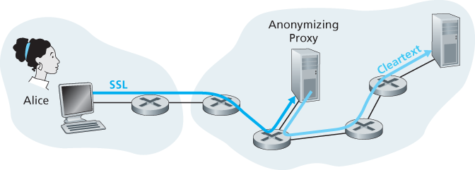
To obtain privacy and anonymity, you can instead use a combination of a trusted proxy server and SSL.
Of course, in this solution, your proxy knows everything: It knows your IP address and the IP address of the site you’re surfing; and it can see all the traffic in cleartext exchanged between you and the Web site. Such a solution, therefore, is only as good as the trustworthiness of the proxy. A more robust approach, taken by the TOR anonymizing and privacy service, is to route your traffic through a series of non-colluding proxy servers [TOR 2016]. In particular, TOR allows independent individuals to contribute proxies to its proxy pool. When a user connects to a server using TOR, TOR randomly chooses (from its proxy pool) a chain of three proxies and routes all traffic between client and server over the chain. In this manner, assuming the proxies do not collude, no one knows that communication took place between your IP address and the target Web site. Furthermore, although cleartext is sent between the last proxy and the server, the last proxy doesn’t know what IP address is sending and receiving the cleartext.
8.9.2 Intrusion Detection Systems
However, to detect many attack types, we need to perform deep packet inspection, that is, look beyond the header fields and into the actual application data that the packets carry. Application gateways often do deep packet inspection. But an application gateway only does this for a specific application.
A device that generates alerts when it observes potentially malicious traffic is called an intrusion detection system (IDS). A device that filters out suspicious traffic is called an intrusion prevention system (IPS).
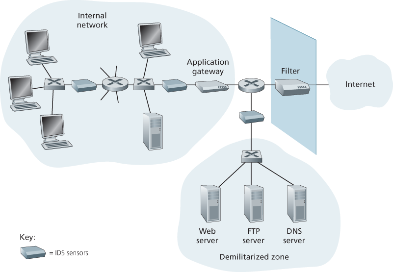
The organization has partitioned its network into two regions: a high-security region, protected by a packet filter and an application gateway and monitored by IDS sensors; and a lower-security region—referred to as the **demilitarized zone (DMZ)**—which is protected only by the packet filter, but also monitored by IDS sensors. Note that the DMZ includes the organization’s servers that need to communicate with the outside world, such as its public Web server and its authoritative DNS server.