Chapter 7 Wireless and Mobile Networks
7.1 Introduction
The base station is a key part of the wireless network infrastructure. Unlike the wireless host and wireless link, a base station has no obvious counterpart in a wired network. A base station is responsible for sending and receiving data (e.g., packets) to and from a wireless host that is associated with that base station. A base station will often be responsible for coordinating the transmission of multiple wireless hosts with which it is associated. When we say a wireless host is “associated” with a base station, we mean that (1) the host is within the wireless communication distance of the base station, and (2) the host uses that base station to relay data between it (the host) and the larger network. Cell towers in cellular networks and access points in 802.11 wireless LANs are examples of base stations.
Hosts associated with a base station are often referred to as operating in infrastructure mode, since all traditional network services (e.g., address assignment and routing) are provided by the network to which a host is connected via the base station. In ad hoc networks, wireless hosts have no such infrastructure with which to connect. In the absence of such infrastructure, the hosts themselves must provide for services such as routing, address assignment, DNS-like name translation, and more.
At the highest level we can classify wireless networks according to two criteria: (i) whether a packet in the wireless network crosses exactly one wireless hop or multiple wireless hops, and (ii) whether there is infrastructure such as a base station in the network:
- Single-hop, infrastructure-based. These networks have a base station that is connected to a larger wired network (e.g., the Internet). Furthermore, all communication is between this base station and a wireless host over a single wireless hop. The 802.11 networks you use in the classroom, café, or library; and the 4G LTE data networks that we will learn about shortly all fall in this category.
- Single-hop, infrastructure-less. In these networks, there is no base station that is connected to a wireless network. However, as we will see, one of the nodes in this single-hop network may coordinate the transmissions of the other nodes. Bluetooth networks and 802.11 networks in ad hoc mode are single-hop, infrastructure-less networks.
- Multi-hop, infrastructure-based. In these networks, a base station is present that is wired to the larger network. However, some wireless nodes may have to relay their communication through other wireless nodes in order to communicate via the base station. Some wireless sensor networks and so-called wireless mesh networks fall in this category.
- Multi-hop, infrastructure-less. There is no base station in these networks, and nodes may have to relay messages among several other nodes in order to reach a destination. Nodes may also be mobile, with connectivity changing among nodes—a class of networks known as mobile ad hoc networks (MANETs). If the mobile nodes are vehicles, the network is a vehicular ad hoc network (VANET).
7.2 Wireless Links and Network Characteristics
A number of important differences between a wired link and a wireless link:
- Decreasing signal strength. Electromagnetic radiation attenuates as it passes through matter (e.g., a radio signal passing through a wall). Even in free space, the signal will disperse, resulting in decreased signal strength (sometimes referred to as path loss) as the distance between sender and receiver increases.
- Interference from other sources. Radio sources transmitting in the same frequency band will interfere with each other. For example, 2.4 GHz wireless phones and 802.11b wireless LANs transmit in the same frequency band.
- Multipath propagation. Multipath propagation occurs when portions of the electromagnetic wave reflect off objects and the ground, taking paths of different lengths between a sender and receiver. This results in the blurring of the received signal at the receiver. Moving objects between the sender and receiver can cause multipath propagation to change over time.
Bit errors will be more common in wireless links than in wired links. For this reason, it is perhaps not surprising that wireless link protocols employ not only powerful CRC error detection codes, but also link-level reliable-data-transfer protocols that retransmit corrupted frames.
This host receives an electromagnetic signal that is a combination of a degraded form of the original signal transmitted by the sender and background noise in the environment. The signal-to-noise ratio (SNR) is a relative measure of the strength of the received signal (i.e., the information being transmitted) and this noise. The SNR is typically measured in units of decibels (dB), a unit of measure that some think is used by electrical engineers primarily to confuse computer scientists. The SNR, measured in dB, is twenty times the ratio of the base-10 logarithm of the amplitude of the received signal to the amplitude of the noise.
Several physical-layer characteristics that are important in understanding higher-layer wireless communication protocols:
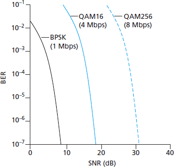
- For a given modulation scheme, the higher the SNR, the lower the BER. Since a sender can increase the SNR by increasing its transmission power, a sender can decrease the probability that a frame is received in error by increasing its transmission power. Note, however, that there is arguably little practical gain in increasing the power beyond a certain threshold, say to decrease the BER from
to . - For a given SNR, a modulation technique with a higher bit transmission rate (whether in error or not) will have a higher BER.
- Dynamic selection of the physical-layer modulation technique can be used to adapt the modulation technique to channel conditions. The SNR (and hence the BER) may change as a result of mobility or due to changes in the environment. Adaptive modulation and coding are used in cellular data systems and in the 802.11 WiFi and 4G cellular data networks. This allows, for example, the selection of a modulation technique that provides the highest transmission rate possible subject to a constraint on the BER, for given channel characteristics.
7.2.1 CDMA
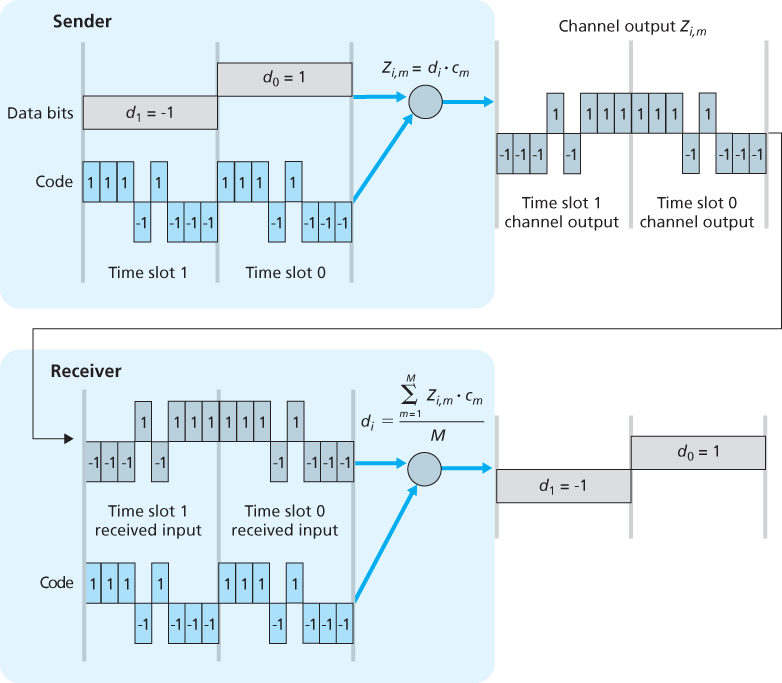
In a CDMA protocol, each bit being sent is encoded by multiplying the bit by a signal (the code) that changes at a much faster rate (known as the chipping rate) than the original sequence of data bits.
For the
In a simple world, with no interfering senders, the receiver would receive the encoded bits,
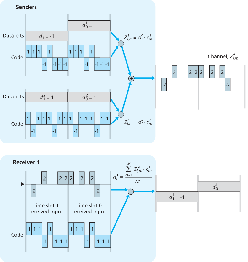
The world is far from ideal, however, and as noted above, CDMA must work in the presence of interfering senders that are encoding and transmitting their data using a different assigned code. CDMA works under the assumption that the interfering transmitted bit signals are additive. This means, for example, that if three senders send a 1 value, and a fourth sender sends a -1 value during the same mini-slot, then the received signal at all receivers during that mini-slot is a 2 (since 1 + 1 + 1 - 1 = 2). In the presence of multiple senders, sender s computes its encoded transmissions,
Amazingly, if the senders’ codes are chosen carefully, each receiver can recover the data sent by a given sender out of the aggregate signal simply by using the sender’s code in exactly the same manner
7.3 WiFi: 802.11 Wireless LANs
There are several 802.11 standards for wireless LAN technology in the IEEE 802.11 (“WiFi”) family. The different 802.11 standards all share some common characteristics. They all use the same medium access protocol, CSMA/CA. All three use the same frame structure for their link-layer frames as well. All three standards have the ability to reduce their transmission rate in order to reach out over greater distances. And, importantly, 802.11 products are also all backwards compatible, meaning, for example, that a mobile capable only of 802.11g may still interact with a newer 802.11ac base station.
802.11 devices operate in two difference frequency ranges: 2.4–2.485 GHz (referred to as the 2.4 GHz range) and 5.1 – 5.8 GHz (referred to as the 5 GHz range). The 2.4 GHz range is an unlicensed frequency band, where 802.11 devices may compete for frequency spectrum with 2.4 GHz phones and microwave ovens. At 5 GHz, 802.11 LANs have a shorter transmission distance for a given power level and suffer more from multipath propagation. The two most recent standards, 802.11n [IEEE 802.11n 2012] and 802.11ac [IEEE 802.11ac 2013; Cisco 802.11ac 2015] uses multiple input multiple-output (MIMO) antennas; i.e., two or more antennas on the sending side and two or more antennas on the receiving side that are transmitting/receiving different signals [Diggavi 2004]. 802.11ac base stations may transmit to multiple stations simultaneously, and use “smart” antennas to adaptively beamform to target transmissions in the direction of a receiver. This decreases interference and increases the distance reached at a given data rate.
| Standard | Frequency Range | Data Rate |
|---|---|---|
| 802.11b | 2.4 GHz | up to 11 Mbps |
| 802.11a | 5 GHz | up to 54 Mbps |
| 802.11g | 2.4 GHz | up to 54 Mbps |
| 802.11n | 2.5 GHz and 5 GHz | up to 450 Mbps |
| 802.11ac | 5 GHz | up to 1300 Mbps |
7.3.1 The 802.11 Architecture
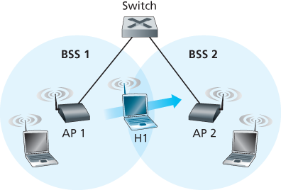
The fundamental building block of the 802.11 architecture is the basic service set (BSS). A BSS contains one or more wireless stations and a central base station, known as an access point (AP) in 802.11 parlance.
As with Ethernet devices, each 802.11 wireless station has a 6-byte MAC address that is stored in the firmware of the station’s adapter (that is, 802.11 network interface card). Each AP also has a MAC address for its wireless interface. As with Ethernet, these MAC addresses are administered by IEEE and are (in theory) globally unique.
Channels and Association
To understand channel numbers, recall that 802.11 operates in the frequency range of 2.4 GHz to 2.4835 GHz. Within this 85 MHz band, 802.11 defines 11 partially overlapping channels. Any two channels are non-overlapping if and only if they are separated by four or more channels. In particular, the set of channels 1, 6, and 11 is the only set of three non-overlapping channels.
The 802.11 standard requires that an AP periodically send beacon frames, each of which includes the AP’s SSID and MAC address. Your wireless device, knowing that APs are sending out beacon frames, scans the 11 channels, seeking beacon frames from any APs that may be out there.
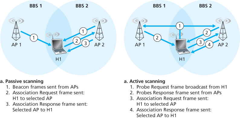
The process of scanning channels and listening for beacon frames is known as passive scanning. A wireless device can also perform active scanning, by broadcasting a probe frame that will be received by all APs within the wireless device’s range.
7.3.2 The 802.11 MAC Protocol
The designers of 802.11 chose a random access protocol for 802.11 wireless LANs. This random access protocol is referred to as CSMA with collision avoidance, or more succinctly as CSMA/CA.
Ethernet and 802.11 use carrier-sensing random access, the two MAC protocols have important differences. First, instead of using collision detection, 802.11 uses collision-avoidance techniques. Second, because of the relatively high bit error rates of wireless channels, 802.11 (unlike Ethernet) uses a link-layer acknowledgment/retransmission (ARQ) scheme.
Unlike the 802.3 Ethernet protocol, the 802.11 MAC protocol does not implement collision detection. There are two important reasons for this:
- The ability to detect collisions requires the ability to send (the station’s own signal) and receive (to determine whether another station is also transmitting) at the same time. Because the strength of the received signal is typically very small compared to the strength of the transmitted signal at the 802.11 adapter, it is costly to build hardware that can detect a collision.
- More importantly, even if the adapter could transmit and listen at the same time (and presumably abort transmission when it senses a busy channel), the adapter would still not be able to detect all collisions, due to the hidden terminal problem and fading.
Because 802.11 wireless LANs do not use collision detection, once a station begins to transmit a frame, it transmits the frame in its entirety; that is, once a station gets started, there is no turning back. As one might expect, transmitting entire frames (particularly long frames) when collisions are prevalent can significantly degrade a multiple access protocol’s performance.
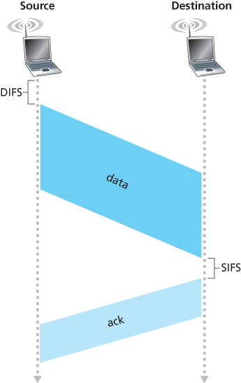
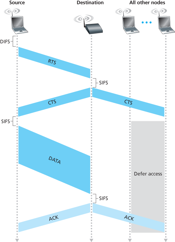
When the destination station receives a frame that passes the CRC, it waits a short period of time known as the Short Inter-frame Spacing (SIFS) and then sends back an acknowledgment frame. If the transmitting station does not receive an acknowledgment within a given amount of time, it assumes that an error has occurred and retransmits the frame, using the CSMA/CA protocol to access the channel. If an acknowledgment is not received after some fixed number of retransmissions, the transmitting station gives up and discards the frame.
Suppose that a station (wireless device or an AP) has a frame to transmit:
- If initially the station senses the channel idle, it transmits its frame after a short period of time known as the Distributed Inter-frame Space (DIFS).
- Otherwise, the station chooses a random backoff value using binary exponential backoff and counts down this value after DIFS when the channel is sensed idle. While the channel is sensed busy, the counter value remains frozen.
- When the counter reaches zero (note that this can only occur while the channel is sensed idle), the station transmits the entire frame and then waits for an acknowledgment.
- If an acknowledgment is received, the transmitting station knows that its frame has been correctly received at the destination station. If the station has another frame to send, it begins the CSMA/CA protocol at step 2. If the acknowledgment isn’t received, the transmitting station reenters the backoff phase in step 2, with the random value chosen from a larger interval.
Of course, collisions can still occur with 802.11 in this scenario: The two stations could be hidden from each other, or the two stations could choose random backoff values that are close enough that the transmission from the station starting first have yet to reach the second station.
Dealing with Hidden Terminals: RTS and CTS
The 802.11 MAC protocol also includes a nifty (but optional) reservation scheme that helps avoid collisions even in the presence of hidden terminals.
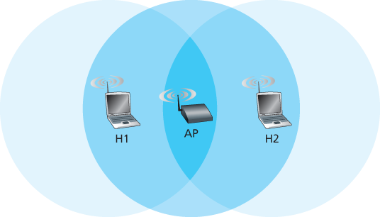
The IEEE 802.11 protocol allows a station to use a short Request to Send (RTS) control frame and a short Clear to Send (CTS) control frame to reserve access to the channel. When a sender wants to send a DATA frame, it can first send an RTS frame to the AP, indicating the total time required to transmit the DATA frame and the acknowledgment (ACK) frame. When the AP receives the RTS frame, it responds by broadcasting a CTS frame. This CTS frame serves two purposes: It gives the sender explicit permission to send and also instructs the other stations not to send for the reserved duration.
Although the RTS/CTS exchange can help reduce collisions, it also introduces delay and consumes channel resources. For this reason, the RTS/CTS exchange is only used (if at all) to reserve the channel for the transmission of a long DATA frame. In practice, each wireless station can set an RTS threshold such that the RTS/CTS sequence is used only when the frame is longer than the threshold. For many wireless stations, the default RTS threshold value is larger than the maximum frame length, so the RTS/CTS sequence is skipped for all DATA frames sent.
7.3.3 The IEEE 802.11 Frame
Although the 802.11 frame shares many similarities with an Ethernet frame, it also contains a number of fields that are specific to its use for wireless links.
Payload and CRC Fields
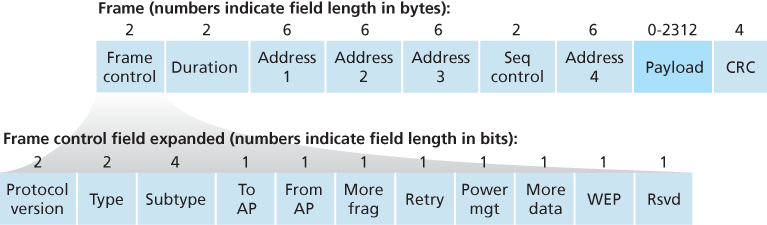
At the heart of the frame is the payload, which typically consists of an IP datagram or an ARP packet. Although the field is permitted to be as long as 2,312 bytes, it is typically fewer than 1,500 bytes, holding an IP datagram or an ARP packet. As with an Ethernet frame, an 802.11 frame includes a 32-bit cyclic redundancy check (CRC) so that the receiver can detect bit errors in the received frame.
Address Fields
Perhaps the most striking difference in the 802.11 frame is that it has four address fields, each of which can hold a 6-byte MAC address. The fourth address field is used when APs forward frames to each other in ad hoc mode.
- Address 2 is the MAC address of the station that transmits the frame. Thus, if a wireless station transmits the frame, that station’s MAC address is inserted in the address 2 field. Similarly, if an AP transmits the frame, the AP’s MAC address is inserted in the address 2 field.
- Address 1 is the MAC address of the wireless station that is to receive the frame. Thus if a mobile wireless station transmits the frame, address 1 contains the MAC address of the destination AP. Similarly, if an AP transmits the frame, address 1 contains the MAC address of the destination wireless station.g
- Address 3 contains the MAC address of this router interface.
Sequence Number, Duration, and Frame Control Fields
Because acknowledgments can get lost, the sending station may send multiple copies of a given frame. The use of sequence numbers allows the receiver to distinguish between a newly transmitted frame and the retransmission of a previous frame.
The 802.11 protocol allows a transmitting station to reserve the channel for a period of time that includes the time to transmit its data frame and the time to transmit an acknowledgment. This duration value is included in the frame’s duration field (both for data frames and for the RTS and CTS frames).
7.3.4 Mobility in the Same IP Subnet
7.3.6 Personal Area Networks: Bluetooth and Zigbee
Bluetooth
802.15.1 networks are sometimes referred to as wireless personal area networks (WPANs). The link and physical layers of 802.15.1 are based on the earlier Bluetooth specification for personal area networks [Held 2001, Bisdikian 2001]. 802.15.1 networks operate in the 2.4 GHz unlicensed radio band in a TDM manner, with time slots of 625 microseconds. During each time slot, a sender transmits on one of 79 channels, with the channel changing in a known but pseudo-random manner from slot to slot. This form of channel hopping, known as frequency-hopping spread spectrum (FHSS), spreads transmissions in time over the frequency spectrum. 802.15.1 can provide data rates up to 4 Mbps.
802.15.1 networks are ad hoc networks: No network infrastructure (e.g., an access point) is needed to interconnect 802.15.1 devices. Thus, 802.15.1 devices must organize themselves. 802.15.1 devices are first organized into a piconet of up to eight active devices. One of these devices is designated as the master, with the remaining devices acting as slaves. The master node truly rules the piconet—its clock determines time in the piconet, it can transmit in each odd-numbered slot, and a slave can transmit only after the master has communicated with it in the previous slot and even then the slave can only transmit to the master. In addition to the slave devices, there can also be up to 255 parked devices in the network. These devices cannot communicate until their status has been changed from parked to active by the master node.
Zigbee
Nodes in a Zigbee network come in two flavors. So-called “reduced-function devices” operate as slave devices under the control of a single “full-function device”, much as Bluetooth slave devices. A full-function device can operate as a master device as in Bluetooth by controlling multiple slave devices, and multiple full-function devices can additionally be configured into a mesh network in which full-function devices route frames amongst themselves. Zigbee shares many protocol mechanisms that we’ve already encountered in other link-layer protocols: beacon frames and link-layer acknowledgments (similar to 802.11), carrier-sense random access protocols with binary exponential backoff (similar to 802.11 and Ethernet), and fixed, guaranteed allocation of time slots (similar to DOCSIS).
7.4 Cellular Internet Access
7.4.1 An Overview of Cellular Network Architecture
Cellular Network Architecture, 2G: Voice Connections to the Telephone Network
GSM has its own particular nomenclature. Each cell contains a base transceiver station (BTS) that transmits signals to and receives signals from the mobile stations in its cell.
The GSM standard for 2G cellular systems uses combined FDM/TDM (radio) for the air interface. In combined FDM/TDM systems, the channel is partitioned into a number of frequency sub-bands; within each sub-band, time is partitioned into frames and slots. Thus, for a combined FDM/TDM system, if the channel is partitioned into F sub-bands and time is partitioned into T slots, then the channel will be able to support F.T simultaneous calls. GSM systems consist of 200-kHz frequency bands with each band supporting eight TDM calls. GSM encodes speech at 13 kbps and 12.2 kbps.
A GSM network’s base station controller (BSC) will typically service several tens of base transceiver stations. The role of the BSC is to allocate BTS radio channels to mobile subscribers, perform paging (finding the cell in which a mobile user is resident), and perform handoff of mobile users. The base station controller and its controlled base transceiver stations collectively constitute a GSM base station subsystem (BSS).
The mobile switching center (MSC) plays the central role in user authorization and accounting (e.g., determining whether a mobile device is allowed to connect to the cellular network), call establishment and teardown, and handoff. A single MSC will typically contain up to five BSCs, resulting in approximately 200K subscribers per MSC. A cellular provider’s network will have a number of MSCs, with special MSCs known as gateway MSCs connecting the provider’s cellular network to the larger public telephone network.
7.4.2 3G Cellular Data Networks: Extending the Internet to Cellular Subscribers
3G Core Network
There are two types of nodes in the 3G core network: Serving GPRS Support Nodes (SGSNs) and Gateway GPRS Support Nodes (GGSNs). GPRS stands for Generalized Packet Radio Service, an early cellular data service in 2G networks. An SGSN is responsible for delivering datagrams to/from the mobile nodes in the radio access network to which the SGSN is attached. The SGSN interacts with the cellular voice network’s MSC for that area, providing user authorization and handoff, maintaining location (cell) information about active mobile nodes, and performing datagram forwarding between mobile nodes in the radio access network and a GGSN. The GGSN acts as a gateway, connecting multiple SGSNs into the larger Internet.
3G Radio Access Network: The Wireless Edge
The 3G radio access network is the wireless first-hop network that we see as a 3G user. The Radio Network Controller (RNC) typically controls several cell base transceiver stations similar to the base stations that we encountered in 2G systems (but officially known in 3G UMTS parlance as a “Node Bs”—a rather non-descriptive name!). Each cell’s wireless link operates between the mobile nodes and a base transceiver station, just as in 2G networks. The RNC connects to both the circuit-switched cellular voice network via an MSC, and to the packet-switched Internet via an SGSN. Thus, while 3G cellular voice and cellular data services use different core networks, they share a common first/last-hop radio access network.
A significant change in 3G UMTS over 2G networks is that rather than using GSM’s FDMA/TDMA scheme, UMTS uses a CDMA technique known as Direct Sequence Wideband CDMA (DS-WCDMA) [Dahlman 1998] within TDMA slots; TDMA slots, in turn, are available on multiple frequencies. The data service associated with the WCDMA specification is known as HSPA (High Speed Packet Access) and promises downlink data rates of up to 14 Mbps.
7.4.3 On to 4G: LTE
4G System Architecture: An All-IP Core Network
There are two important high-level observations about the 4G architecture:
- A unified, all-IP network architecture. Unlike the 3G network, which has separate network components and paths for voice and data traffic, the 4G architecture is “all-IP”—both voice and data are carried in IP datagrams to/from the wireless device (the User Equipment, UE in 4G parlance) to the gateway to the packet gateway (P-GW) that connects the 4G edge network to the rest of the network.
- A clear separation of the 4G data plane and 4G control plane.
- A clear separation between the radio access network, and the all-IP-core network.
The principal components of the 4G architecture are as follows:
- The eNodeB is the logical descendant of the 2G base station and the 3G Radio Network Controller (a.k.a Node B) and again plays a central role here. Its data-plane role is to forward datagrams between UE (over the LTE radio access network) and the P-GW. UE datagrams are encapsulated at the eNodeB and tunneled to the P-GW through the 4G network’s all-IP enhanced packet core (EPC). This tunneling between the eNodeB and P-GW is similar the tunneling of IPv6 datagrams between two IPv6 endpoints through a network of IPv4 routers. These tunnels may have associated quality of service (QoS) guarantees. In the control plane, the eNodeB handles registration and mobility signaling traffic on behalf of the UE.
- The Packet Data Network Gateway (P-GW) allocates IP addresses to the UEs and performs QoS enforcement. As a tunnel endpoint it also performs datagram encapsulation/decapsulation when forwarding a datagram to/from a UE.
- The Serving Gateway (S-GW) is the data-plane mobility anchor point—all UE traffic will pass through the S-GW. The S-GW also performs charging/billing functions and lawful traffic interception.
- The Mobility Management Entity (MME) performs connection and mobility management on behalf of the UEs resident in the cell it controls. It receives UE subscription information from the HHS. We cover mobility in cellular networks.
- The Home Subscriber Server (HSS) contains UE information including roaming access capabilities, quality of service profiles, and authentication information.
LTE Radio Access Network
LTE uses a combination of frequency division multiplexing and time division multiplexing on the downstream channel, known as orthogonal frequency division multiplexing (OFDM) [Rohde 2008; Ericsson 2011]. In LTE, each active mobile node is allocated one or more 0.5 ms time slots in one or more of the channel frequencies. By being allocated increasingly more time slots (whether on the same frequency or on different frequencies), a mobile node is able to achieve increasingly higher transmission rates. Slot (re)allocation among mobile nodes can be performed as often as once every millisecond.
The particular allocation of time slots to mobile nodes is not mandated by the LTE standard. Instead, the decision of which mobile nodes will be allowed to transmit in a given time slot on a given frequency is determined by the scheduling algorithms provided by the LTE equipment vendor and/or the network operator.
7.5 Mobility Management: Principles
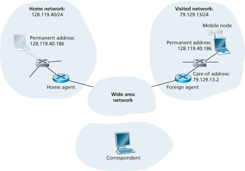
In a network setting, the permanent home of a mobile node (such as a laptop or smartphone) is known as the home network, and the entity within the home network that performs the mobility management functions discussed below on behalf of the mobile node is known as the home agent. The network in which the mobile node is currently residing is known as the foreign (or visited) network, and the entity within the foreign network that helps the mobile node with the mobility management functions discussed below is known as a foreign agent. A correspondent is the entity wishing to communicate with the mobile node.
7.5.1 Addressing
When a mobile node is resident in a foreign network, all traffic addressed to the node’s permanent address now needs to be routed to the foreign network. One option is for the foreign network to advertise to all other networks that the mobile node is resident in its network. This could be via the usual exchange of intradomain and interdomain routing information and would require few changes to the existing routing infrastructure. The foreign network could simply advertise to its neighbors that it has a highly specific route to the mobile node’s permanent address. These neighbors would then propagate this routing information throughout the network as part of the normal procedure of updating routing information and forwarding tables. When the mobile node leaves one foreign network and joins another, the new foreign network would advertise a new, highly specific route to the mobile node, and the old foreign network would withdraw its routing information regarding the mobile node.
An alternative approach (and one that has been adopted in practice) is to push mobility functionality from the network core to the network edge—a recurring theme in our study of Internet architecture. A natural way to do this is via the mobile node’s home network. A protocol between the mobile node (or a foreign agent representing the mobile node) and the home agent will certainly be needed to update the mobile node’s location.
One role of the foreign agent is to create a so-called care-of address (COA) for the mobile node, with the network portion of the COA matching that of the foreign network. There are thus two addresses associated with a mobile node, its permanent address (analogous to our mobile youth’s family’s home address) and its COA, sometimes known as a foreign address (analogous to the address of the house in which our mobile youth is currently residing). A second role of the foreign agent is to inform the home agent that the mobile node is resident in its (the foreign agent’s) network and has the given COA.
7.5.2 Routing to a Mobile Node
Indirect Routing to a Mobile Node
In the indirect routing approach, the correspondent simply addresses the datagram to the mobile node’s permanent address and sends the datagram into the network, blissfully unaware of whether the mobile node is resident in its home network or is visiting a foreign network; mobility is thus completely transparent to the correspondent. Such datagrams are first routed, as usual, to the mobile node’s home network.
In addition to being responsible for interacting with a foreign agent to track the mobile node’s COA, the home agent has another very important function. Its second job is to be on the lookout for arriving datagrams addressed to nodes whose home network is that of the home agent but that are currently resident in a foreign network. The home agent intercepts these datagrams and then forwards them to a mobile node in a two-step process. The datagram is first forwarded to the foreign agent, using the mobile node’s COA, and then forwarded from the foreign agent to the mobile node.
The home agent will need to address the datagram using the mobile node’s COA, so that the network layer will route the datagram to the foreign network. On the other hand, it is desirable to leave the correspondent’s datagram intact, since the application receiving the datagram should be unaware that the datagram was forwarded via the home agent. Both goals can be satisfied by having the home agent encapsulate the correspondent’s original complete datagram within a new (larger) datagram. This larger datagram is addressed and delivered to the mobile node’s COA. The foreign agent, who “owns” the COA, will receive and decapsulate the datagram—that is, remove the correspondent’s original datagram from within the larger encapsulating datagram and forward the original datagram to the mobile node.
Let’s summarize our discussion of indirect routing by listing the new network-layer functionality required to support mobility:
- A mobile-node–to–foreign-agent protocol.
- A foreign-agent–to–home-agent registration protocol.
- A home-agent datagram encapsulation protocol.
- A foreign-agent decapsulation protocol.
As long as the time between the mobile node’s disconnection from network A (at which point it can no longer receive datagrams via A) and its attachment to network B (at which point it will register a new COA with its home agent) is small, few datagrams will be lost. End-to-end connections can suffer datagram loss due to network congestion. Hence occasional datagram loss within a connection when a node moves between networks is by no means a catastrophic problem. If loss-free communication is required, upper-layer mechanisms will recover from datagram loss, whether such loss results from network congestion or from user mobility.
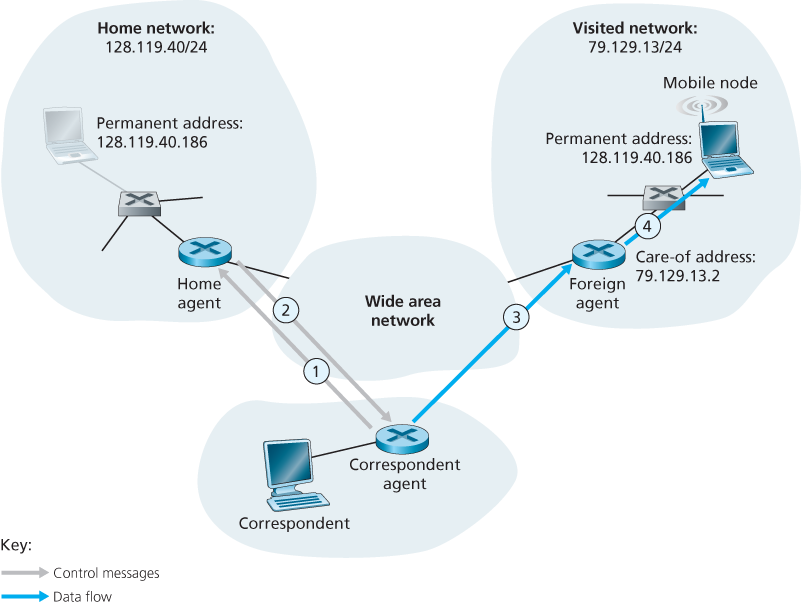
Direct Routing to a Mobile Node
In the direct routing approach, a correspondent agent in the correspondent’s network first learns the COA of the mobile node. This can be done by having the correspondent agent query the home agent, assuming that (as in the case of indirect routing) the mobile node has an up-to-date value for its COA registered with its home agent. It is also possible for the correspondent itself to perform the function of the correspondent agent, just as a mobile node could perform the function of the foreign agent.
It introduces two important additional challenges:
- A mobile-user location protocol is needed for the correspondent agent to query the home agent to obtain the mobile node’s COA.
- When the mobile node moves from one foreign network to another, how will data now be forwarded to the new foreign network? In the case of indirect routing, this problem was easily solved by updating the COA maintained by the home agent. However, with direct routing, the home agent is queried for the COA by the correspondent agent only once, at the beginning of the session. Thus, updating the COA at the home agent, while necessary, will not be enough to solve the problem of routing data to the mobile node’s new foreign network.
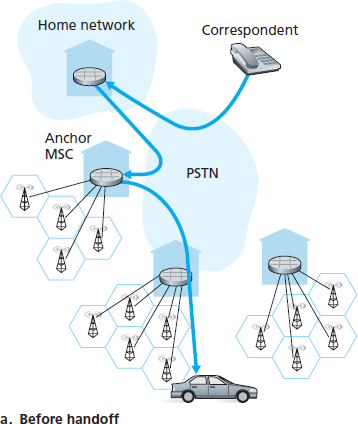
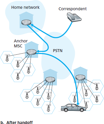
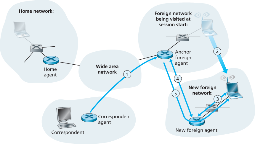
One solution would be to create a new protocol to notify the correspondent of the changing COA. An alternate solution, and one that we’ll see adopted in practice in GSM networks, works as follows. Suppose data is currently being forwarded to the mobile node in the foreign network where the mobile node was located when the session first started. We’ll identify the foreign agent in that foreign network where the mobile node was first found as the anchor foreign agent. When the mobile node moves to a new foreign network, the mobile node registers with the new foreign agent, and the new foreign agent provides the anchor foreign agent with the mobile node’s new COA. When the anchor foreign agent receives an encapsulated datagram for a departed mobile node, it can then re-encapsulate the datagram and forward it to the mobile node using the new COA. If the mobile node later moves yet again to a new foreign network, the foreign agent in that new visited network would then contact the anchor foreign agent in order to set up forwarding to this new foreign network.
7.6 Mobile IP
The Internet architecture and protocols for supporting mobility, collectively known as mobile IP, are defined primarily in RFC 5944 for IPv4.
Agent Discovery
A mobile IP node arriving to a new network, whether attaching to a foreign network or returning to its home network, must learn the identity of the corresponding foreign or home agent. Indeed it is the discovery of a new foreign agent, with a new network address, that allows the network layer in a mobile node to learn that it has moved into a new foreign network. This process is known as agent discovery. Agent discovery can be accomplished in one of two ways: via agent advertisement or via agent solicitation.
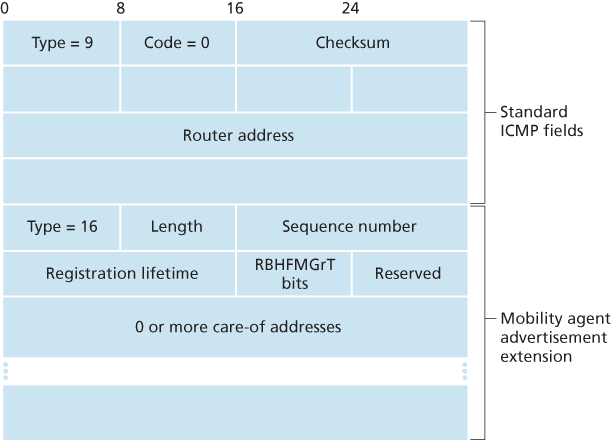
With agent advertisement, a foreign or home agent advertises its services using an extension to the existing router discovery protocol [RFC 1256]. The agent periodically broadcasts an ICMP message with a type field of 9 (router discovery) on all links to which it is connected. The router discovery message contains the IP address of the router (that is, the agent), thus allowing a mobile node to learn the agent’s IP address. The router discovery message also contains a mobility agent advertisement extension that contains additional information needed by the mobile node. Among the more important fields in the extension are the following:
- Home agent bit (H). Indicates that the agent is a home agent for the network in which it resides.
- Foreign agent bit (F). Indicates that the agent is a foreign agent for the network in which it resides.
- Registration required bit (R). Indicates that a mobile user in this network must register with a foreign agent. In particular, a mobile user cannot obtain a care-of address in the foreign network (for example, using DHCP) and assume the functionality of the foreign agent for itself, without registering with the foreign agent.
- M, G encapsulation bits. Indicate whether a form of encapsulation other than IP-in-IP encapsulation will be used.
- Care-of address (COA) fields. A list of one or more care-of addresses provided by the foreign agent. In our example below, the COA will be associated with the foreign agent, who will receive datagrams sent to the COA and then forward them to the appropriate mobile node. The mobile user will select one of these addresses as its COA when registering with its home agent.
With agent solicitation, a mobile node wanting to learn about agents without waiting to receive an agent advertisement can broadcast an agent solicitation message, which is simply an ICMP message with type value 10. An agent receiving the solicitation will unicast an agent advertisement directly to the mobile node, which can then proceed as if it had received an unsolicited advertisement.
Registration with the Home Agent
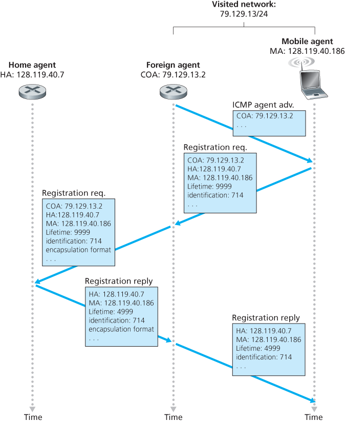
Once a mobile IP node has received a COA, that address must be registered with the home agent. This can be done either via the foreign agent (who then registers the COA with the home agent) or directly by the mobile IP node itself. Four steps are involved.
- Following the receipt of a foreign agent advertisement, a mobile node sends a mobile IP registration message to the foreign agent. The registration message is carried within a UDP datagram and sent to port 434. The registration message carries a COA advertised by the foreign agent, the address of the home agent (HA), the permanent address of the mobile node (MA), the requested lifetime of the registration, and a 64-bit registration identification. The requested registration lifetime is the number of seconds that the registration is to be valid. If the registration is not renewed at the home agent within the specified lifetime, the registration will become invalid. The registration identifier acts like a sequence number and serves to match a received registration reply with a registration request.
- The foreign agent receives the registration message and records the mobile node’s permanent IP address. The foreign agent now knows that it should be looking for datagrams containing an encapsulated datagram whose destination address matches the permanent address of the mobile node. The foreign agent then sends a mobile IP registration message (again, within a UDP datagram) to port 434 of the home agent. The message contains the COA, HA, MA, encapsulation format requested, requested registration lifetime, and registration identification.
- The home agent receives the registration request and checks for authenticity and correctness. The home agent binds the mobile node’s permanent IP address with the COA; in the future, datagrams arriving at the home agent and addressed to the mobile node will now be encapsulated and tunneled to the COA. The home agent sends a mobile IP registration reply containing the HA, MA, actual registration lifetime, and the registration identification of the request that is being satisfied with this reply.
- The foreign agent receives the registration reply and then forwards it to the mobile node.
A foreign agent need not explicitly deregister a COA when a mobile node leaves its network. This will occur automatically, when the mobile node moves to a new network (whether another foreign network or its home network) and registers a new COA.
7.7 Managing Mobility in Cellular Networks
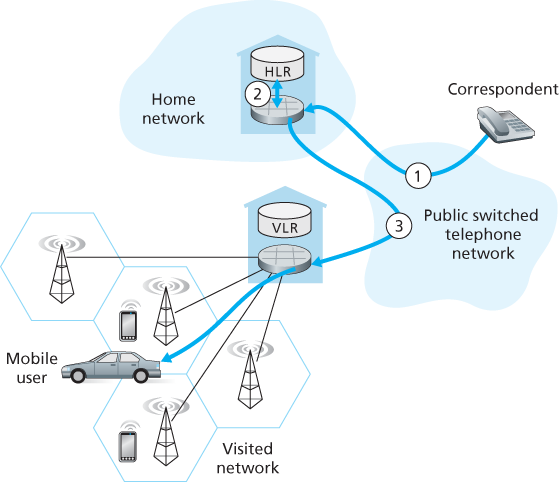
Like mobile IP, GSM adopts an indirect routing approach, first routing the correspondent’s call to the mobile user’s home network and from there to the visited network. In GSM terminology, the mobile users’s home network is referred to as the mobile user’s home public land mobile network (home PLMN). Since the PLMN acronym is a bit of a mouthful, and mindful of our quest to avoid an alphabet soup of acronyms, we’ll refer to the GSM home PLMN simply as the home network. The home network is the cellular provider with which the mobile user has a subscription (i.e., the provider that bills the user for monthly cellular service). The visited PLMN, which we’ll refer to simply as the visited network, is the network in which the mobile user is currently residing.
As in the case of mobile IP, the responsibilities of the home and visited networks are quite different:
- The home network maintains a database known as the home location register (HLR), which contains the permanent cell phone number and subscriber profile information for each of its subscribers. Importantly, the HLR also contains information about the current locations of these subscribers. That is, if a mobile user is currently roaming in another provider’s cellular network, the HLR contains enough information to obtain (via a process we’ll describe shortly) an address in the visited network to which a call to the mobile user should be routed. As we’ll see, a special switch in the home network, known as the Gateway Mobile services Switching Center (GMSC) is contacted by a correspondent when a call is placed to a mobile user. Again, in our quest to avoid an alphabet soup of acronyms, we’ll refer to the GMSC here by a more descriptive term, home MSC.
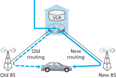
- The visited network maintains a database known as the visitor location register (VLR). The VLR contains an entry for each mobile user that is currently in the portion of the network served by the VLR. VLR entries thus come and go as mobile users enter and leave the network. A VLR is usually co-located with the mobile switching center (MSC) that coordinates the setup of a call to and from the visited network.
7.7.2 Handoffs in GSM