
Chapter 5 The Network Layer: Control Plane
5.1 Introduction
How those forwarding and flow tables are computed, maintained and installed? There are two possible approaches for doing so:
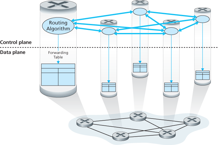
- Per-router control
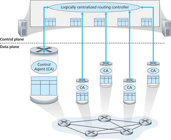
- Logically centralized control
5.2 Routing Algorithms
Routing algorithms, whose goal is to determine good paths (equivalently, routes), from senders to receivers, through the network of routers. Typically, a “good” path is one that has the least cost.
For any edge
Given that costs are assigned to the various edges in the graph abstraction, a natural goal of a routing algorithm is to identify the least costly paths between sources and destinations. To make this problem more precise, recall that a path in a graph
Broadly, one way in which we can classify routing algorithms is according to whether they are centralized or decentralized.
- A centralized routing algorithm computes the least-cost path between a source and destination using complete, global knowledge about the network. That is, the algorithm takes the connectivity between all nodes and all link costs as inputs. This then requires that the algorithm somehow obtain this information before actually performing the calculation. The calculation itself can be run at one site or could be replicated in the routing component of each and every router. Algorithms with global state information are often referred to as link-state (LS) algorithms, since the algorithm must be aware of the cost of each link in the network.
- In a decentralized routing algorithm, the calculation of the least-cost path is carried out in an iterative, distributed manner by the routers. No node has complete information about the costs of all network links. Instead, each node begins with only the knowledge of the costs of its own directly attached links. Then, through an iterative process of calculation and exchange of information with its neighboring nodes, a node gradually calculates the least-cost path to a destination or set of destinations. The decentralized routing algorithm is called a distance-vector (DV) algorithm, because each node maintains a vector of estimates of the costs (distances) to all other nodes in the network. Such decentralized algorithms, with interactive message exchange between neighboring routers is perhaps more naturally suited to control planes where the routers interact directly with each other.
A second broad way to classify routing algorithms is according to whether they are static or dynamic. In static routing algorithms, routes change very slowly over time, often as a result of human intervention (for example, a human manually editing a link costs). Dynamic routing algorithms change the routing paths as the network traffic loads or topology change. A dynamic algorithm can be run either periodically or in direct response to topology or link cost changes.
A third way to classify routing algorithms is according to whether they are load-sensitive or load-insensitive. In a load-sensitive algorithm, link costs vary dynamically to reflect the current level of congestion in the underlying link. If a high cost is associated with a link that is currently congested, a routing algorithm will tend to choose routes around such a congested link. Today’s Internet routing algorithms (such as RIP, OSPF, and BGP) are load-insensitive, as a link’s cost does not explicitly reflect its current (or recent past) level of congestion.
5.2.1 The Link-State (LS) Routing Algorithm
In practice this is accomplished by having each node broadcast link-state packets to all other nodes in the network, with each link-state packet containing the identities and costs of its attached links. The result of the nodes’ broadcast is that all nodes have an identical and complete view of the network. Each node can then run the LS algorithm and compute the same set of least-cost paths as every other node.
The link-state routing algorithm we present below is known as Dijkstra’s algorithm, named after its inventor. A closely related algorithm is Prim’s algorithm.
Let us define the following notation:
- D(v): cost of the least-cost path from the source node to destination v as of this iteration of the algorithm.
- p(v): previous node (neighbor of v) along the current least-cost path from the source to v.
- _N_′: subset of nodes; v is in _N_′ if the least-cost path from the source to v is definitively known.
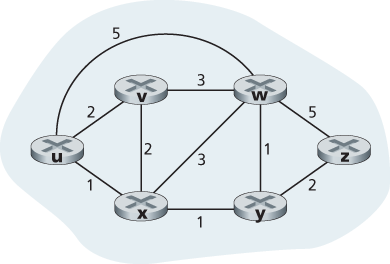
Link-State (LS) Algorithm for Source Node u
| step | N’ | D (v), p (v) | D (w), p (w) | D (x), p (x) | D (y), p (y) | D (z), p (z) |
|---|---|---|---|---|---|---|
| 0 | u | 2, u | 5, u | 1,u | ∞ | ∞ |
| 1 | ux | 2, u | 4, x | 2, x | ∞ | |
| 2 | uxy | 2, u | 3, y | 4, y | ||
| 3 | uxyv | 3, y | 4, y | |||
| 4 | uxyvw | 4, y | ||||
| 5 | uxyvwz |
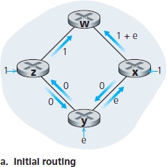
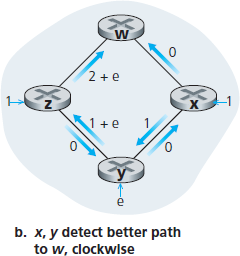
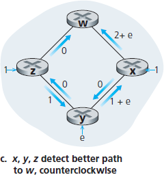
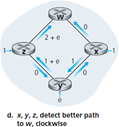
Let us consider a pathology that can arise:
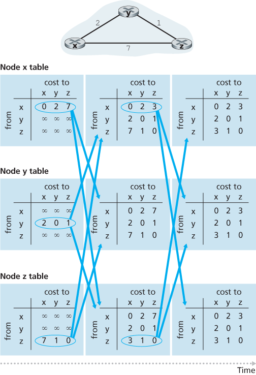
5.2.2 The Distance-Vector (DV) Routing Algorithm
Whereas the LS algorithm is an algorithm using global information, the distance-vector (DV) algorithm is iterative, asynchronous, and distributed.
Let
Another important practical contribution of the Bellman-Ford equation is that it suggests the form of the neighbor-to-neighbor communication that will take place in the DV algorithm.
Each node
- For each neighbor
, the cost from to directly attached neighbor, - Node
’s distance vector, that is, , containing ’s estimate of its cost to all destinations, , in - The distance vectors of each of its neighbors, that is,
for each neighbor of
In the distributed, asynchronous algorithm, from time to time, each node sends a copy of its distance vector to each of its neighbors. When a node
If node
Distance-Vector (DV) Algorithm
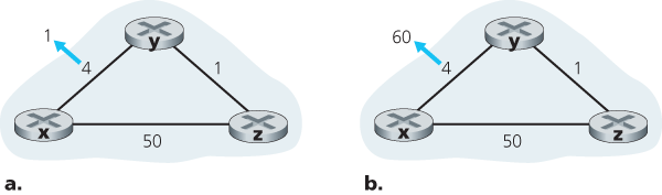
Distance-Vector Algorithm: Link-Cost Changes and Link Failure
Distance-Vector Algorithm: Adding Poisoned Reverse
The specific looping scenario just described can be avoided using a technique known as poisoned reverse. The idea is simple—if
Does poisoned reverse solve the general count-to-infinity problem? It does not. You should convince yourself that loops involving three or more nodes (rather than simply two immediately neighboring nodes) will not be detected by the poisoned reverse technique.
5.3 Intra-AS Routing in the Internet: OSPF
AS(Autonomous systems) consisting of a group of routers that are under the same administrative control. Often the routers in an ISP, and the links that interconnect them, constitute a single AS. Some ISPs, however, partition their network into multiple ASs. An autonomous system is identified by its globally unique autonomous system number (ASN) [RFC 1930]. AS numbers, like IP addresses, are assigned by ICANN regional registries [ICANN 2016].
Routers within the same AS all run the same routing algorithm and have information about each other. The routing algorithm running within an autonomous system is called an intra-autonomous system routing protocol.
Open Shortest Path First (OSPF)
OSPF routing and its closely related cousin, IS-IS, are widely used for intra-AS routing in the Internet. The Open in OSPF indicates that the routing protocol specification is publicly available (for example, as opposed to Cisco’s EIGRP protocol, which was only recently became open [Savage 2015], after roughly 20 years as a Cisco-proprietary protocol). The most recent version of OSPF, version 2, is defined in [RFC 2328], a public document.
OSPF is a link-state protocol that uses flooding of link-state information and a Dijkstra’s least-cost path algorithm. With OSPF, each router constructs a complete topological map (that is, a graph) of the entire autonomous system. Each router then locally runs Dijkstra’s shortest-path algorithm to determine a shortest-path tree to all subnets, with itself as the root node. Individual link costs are configured by the network administrator (see sidebar, Principles and Practice: Setting OSPF Weights). The administrator might choose to set all link costs to 1, thus achieving minimum-hop routing, or might choose to set the link weights to be inversely proportional to link capacity in order to discourage traffic from using low-bandwidth links. OSPF does not mandate a policy for how link weights are set (that is the job of the network administrator), but instead provides the mechanisms (protocol) for determining least-cost path routing for the given set of link weights.
With OSPF, a router broadcasts routing information to all other routers in the autonomous system, not just to its neighboring routers. A router broadcasts link-state information whenever there is a change in a link’s state (for example, a change in cost or a change in up/down status). It also broadcasts a link’s state periodically (at least once every 30 minutes), even if the link’s state has not changed. RFC 2328 notes that “this periodic updating of link state advertisements adds robustness to the link state algorithm.” OSPF advertisements are contained in OSPF messages that are carried directly by IP, with an upper-layer protocol of 89 for OSPF. Thus, the OSPF protocol must itself implement functionality such as reliable message transfer and link-state broadcast. The OSPF protocol also checks that links are operational (via a HELLO message that is sent to an attached neighbor) and allows an OSPF router to obtain a neighboring router’s database of network-wide link state.
Some of the advances embodied in OSPF include the following:
- Security. Exchanges between OSPF routers (for example, link-state updates) can be authenticated. With authentication, only trusted routers can participate in the OSPF protocol within an AS, thus preventing malicious intruders (or networking students taking their newfound knowledge out for a joyride) from injecting incorrect information into router tables. By default, OSPF packets between routers are not authenticated and could be forged. Two types of authentication can be configured—simple and MD5. With simple authentication, the same password is configured on each router. When a router sends an OSPF packet, it includes the password in plaintext. Clearly, simple authentication is not very secure. MD5 authentication is based on shared secret keys that are configured in all the routers. For each OSPF packet that it sends, the router computes the MD5 hash of the content of the OSPF packet appended with the secret key. Then the router includes the resulting hash value in the OSPF packet. The receiving router, using the preconfigured secret key, will compute an MD5 hash of the packet and compare it with the hash value that the packet carries, thus verifying the packet’s authenticity. Sequence numbers are also used with MD5 authentication to protect against replay attacks.
- Multiple same-cost paths. When multiple paths to a destination have the same cost, OSPF allows multiple paths to be used (that is, a single path need not be chosen for carrying all traffic when multiple equal-cost paths exist).
- Integrated support for unicast and multicast routing. Multicast OSPF (MOSPF) [RFC 1584] provides simple extensions to OSPF to provide for multicast routing. MOSPF uses the existing OSPF link database and adds a new type of link-state advertisement to the existing OSPF link-state broadcast mechanism.
- Support for hierarchy within a single AS. An OSPF autonomous system can be configured hierarchically into areas. Each area runs its own OSPF link-state routing algorithm, with each router in an area broadcasting its link state to all other routers in that area. Within each area, one or more area border routers are responsible for routing packets outside the area. Lastly, exactly one OSPF area in the AS is configured to be the backbone area. The primary role of the backbone area is to route traffic between the other areas in the AS. The backbone always contains all area border routers in the AS and may contain non-border routers as well. Inter-area routing within the AS requires that the packet be first routed to an area border router (intra-area routing), then routed through the backbone to the area border router that is in the destination area, and then routed to the final destination.
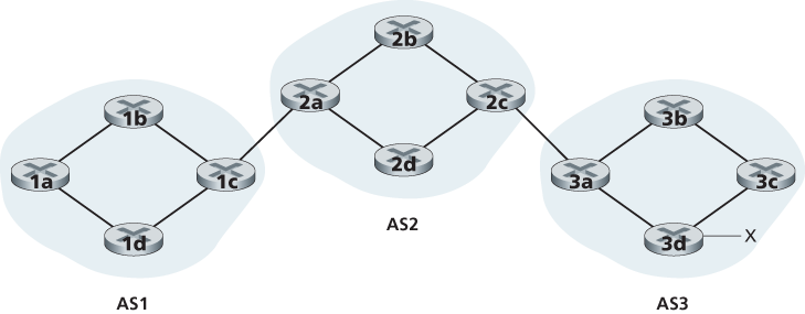
5.4 Routing Among the ISPs: BGP
To route a packet across multiple ASs, say from a smartphone in Timbuktu to a server in a datacenter in Silicon Valley, we need an inter-autonomous system routing protocol. Since an inter-AS routing protocol involves coordination among multiple ASs, communicating ASs must run the same inter-AS routing protocol. In fact, in the Internet, all ASs run the same inter-AS routing protocol, called the Border Gateway Protocol, more commonly known as BGP [RFC 4271; Stewart 1999].
BGP is a decentralized and asynchronous protocol in the vein of distance-vector routing.
5.4.1 The Role of BGP
In BGP, packets are not routed to a specific destination address, but instead to CIDRized prefixes, with each prefix representing a subnet or a collection of subnets. In the world of BGP, a destination may take the form 138.16.68/22, which for this example includes 1,024 IP addresses. Thus, a router’s forwarding table will have entries of the form (x, I), where x is a prefix (such as 138.16.68/22) and I is an interface number for one of the router’s interfaces.
As an inter-AS routing protocol, BGP provides each router a means to:
- Obtain prefix reachability information from neighboring ASs. In particular, BGP allows each subnet to advertise its existence to the rest of the Internet. A subnet screams, “I exist and I am here”, and BGP makes sure that all the routers in the Internet know about this subnet. If it weren’t for BGP, each subnet would be an isolated island—alone, unknown and unreachable by the rest of the Internet.
- Determine the “best” routes to the prefixes. A router may learn about two or more different routes to a specific prefix. To determine the best route, the router will locally run a BGP route-selection procedure (using the prefix reachability information it obtained via neighboring routers). The best route will be determined based on policy as well as the reachability information.
5.4.2 Advertising BGP Route Information
For each AS, each router is either a gateway router or an internal router. A gateway router is a router on the edge of an AS that directly connects to one or more routers in other ASs. An internal router connects only to hosts and routers within its own AS.
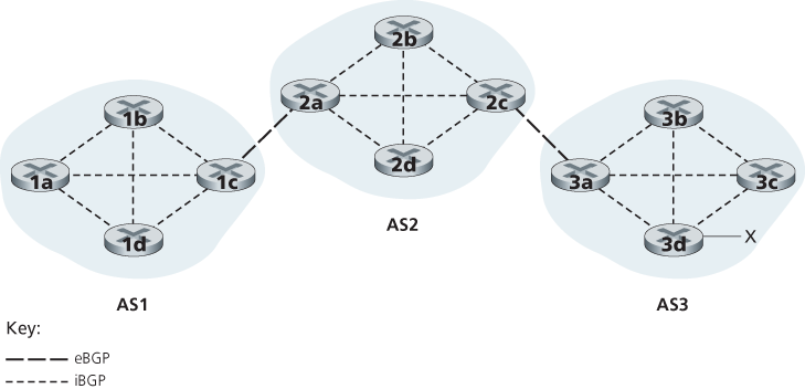
In BGP, pairs of routers exchange routing information over semi-permanent TCP connections using port 179. Each such TCP connection, along with all the BGP messages sent over the connection, is called a BGP connection. Furthermore, a BGP connection that spans two ASs is called an external BGP (eBGP) connection, and a BGP session between routers in the same AS is called an internal BGP (iBGP) connection.
5.4.3 Determining the Best Routes
When a router advertises a prefix across a BGP connection, it includes with the prefix several BGP attributes. In BGP jargon, a prefix along with its attributes is called a route. Two of the more important attributes are AS-PATH and NEXT-HOP. The AS-PATH attribute contains the list of ASs through which the advertisement has passed. To generate the AS-PATH value, when a prefix is passed to an AS, the AS adds its ASN to the existing list in the AS-PATH. BGP routers also use the AS-PATH attribute to detect and prevent looping advertisements; specifically, if a router sees that its own AS is contained in the path list, it will reject the advertisement.
Providing the critical link between the inter-AS and intra-AS routing protocols, the NEXT-HOP attribute has a subtle but important use. The NEXT-HOP is the IP address of the router interface that begins the AS-PATH.
Each BGP route is written as a list with three components: NEXT-HOP; AS-PATH; destination prefix.
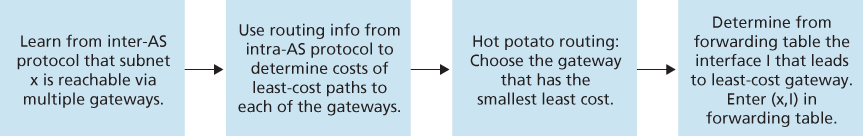
Hot Potato Routing
In hot potato routing, the route chosen (from among all possible routes) is that route with the least cost to the NEXT-HOP router beginning that route.
It is important to note that when adding an outside-AS prefix into a forwarding table, both the inter-AS routing protocol (BGP) and the intra-AS routing protocol (e.g., OSPF) are used.
Route-Selection Algorithm
In practice, BGP uses an algorithm that is more complicated than hot potato routing, but nevertheless incorporates hot potato routing. For any given destination prefix, the input into BGP’s route-selection algorithm is the set of all routes to that prefix that have been learned and accepted by the router. If there is only one such route, then BGP obviously selects that route. If there are two or more routes to the same prefix, then BGP sequentially invokes the following elimination rules until one route remains:
- A route is assigned a local preference value as one of its attributes (in addition to the AS-PATH and NEXT-HOP attributes). The local preference of a route could have been set by the router or could have been learned from another router in the same AS. The value of the local preference attribute is a policy decision that is left entirely up to the AS’s network administrator. The routes with the highest local preference values are selected.
- From the remaining routes (all with the same highest local preference value), the route with the shortest AS-PATH is selected. If this rule were the only rule for route selection, then BGP would be using a DV algorithm for path determination, where the distance metric uses the number of AS hops rather than the number of router hops.
- From the remaining routes (all with the same highest local preference value and the same AS-PATH length), hot potato routing is used, that is, the route with the closest NEXT-HOP router is selected.
- If more than one route still remains, the router uses BGP identifiers to select the route; see [Stewart 1999].
5.4.4 IP-Anycast
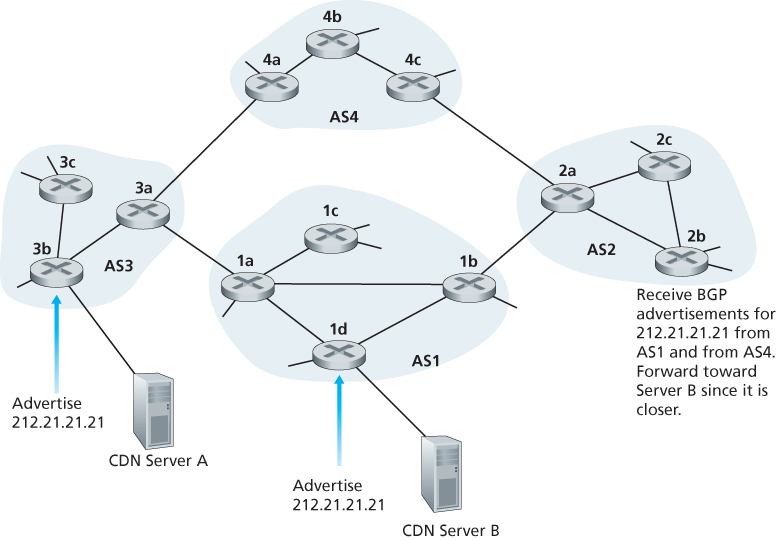
In addition to being the Internet’s inter-AS routing protocol, BGP is often used to implement the IP-anycast service [RFC 1546, RFC 7094], which is commonly used in DNS.
During the IP-anycast configuration stage, the CDN company assigns the same IP address to each of its servers, and uses standard BGP to advertise this IP address from each of the servers. When a BGP router receives multiple route advertisements for this IP address, it treats these advertisements as providing different paths to the same physical location (when, in fact, the advertisements are for different paths to different physical locations). When configuring its routing table, each router will locally use the BGP route-selection algorithm to pick the “best” (for example, closest, as determined by AS-hop counts) route to that IP address. For example, if one BGP route (corresponding to one location) is only one AS hop away from the router, and all other BGP routes (corresponding to other locations) are two or more AS hops away, then the BGP router would choose to route packets to the location that is one hop away. After this initial BGP address-advertisement phase, the CDN can do its main job of distributing content. When a client requests the video, the CDN returns to the client the common IP address used by the geographically dispersed servers, no matter where the client is located. When the client sends a request to that IP address, Internet routers then forward the request packet to the “closest” server, as defined by the BGP route-selection algorithm.
in practice CDNs generally choose not to use IP-anycast because BGP routing changes can result in different packets of the same TCP connection arriving at different instances of the Web server. But IP-anycast is extensively used by the DNS system to direct DNS queries to the closest root DNS server.
5.5 The SDN Control Plane
5.5.2 The SDN Control Plane: SDN Controller and SDN Network-control Applications
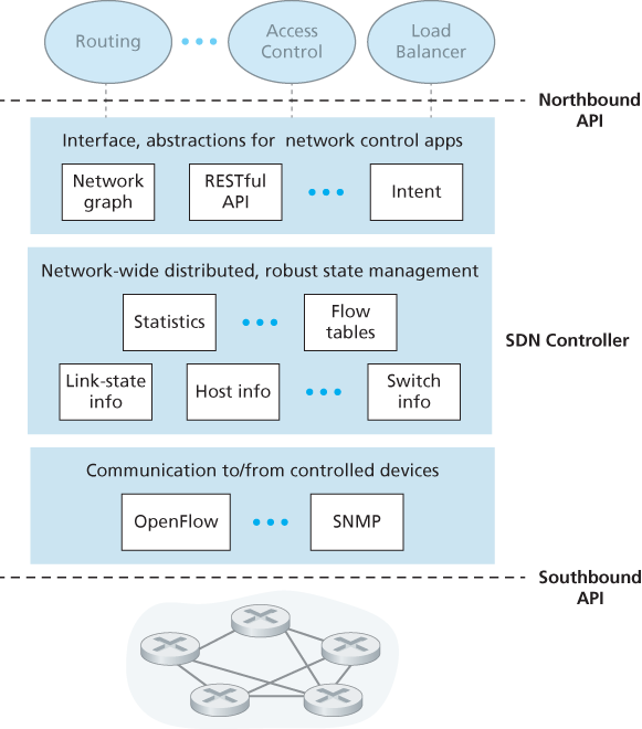
A controller’s functionality can be broadly organized into three layers.
- A communication layer: communicating between the SDN controller and controlled network devices. Clearly, if an SDN controller is going to control the operation of a remote SDN-enabled switch, host, or other device, a protocol is needed to transfer information between the controller and that device. In addition, a device must be able to communicate locally-observed events to the controller (e.g., a message indicating that an attached link has gone up or down, that a device has just joined the network, or a heartbeat indicating that a device is up and operational). These events provide the SDN controller with an up-to-date view of the network’s state. This protocol constitutes the lowest layer of the controller architecture. The communication between the controller and the controlled devices cross what has come to be known as the controller’s “southbound” interface. OpenFlow is implemented in most, if not all, SDN controllers.
- A network-wide state-management layer. The ultimate control decisions made by the SDN control plane—e.g., configuring flow tables in all switches to achieve the desired end-end forwarding, to implement load balancing, or to implement a particular firewalling capability—will require that the controller have up-to-date information about state of the networks’ hosts, links, switches, and other SDN-controlled devices. A switch’s flow table contains counters whose values might also be profitably used by network-control applications; these values should thus be available to the applications. Since the ultimate aim of the control plane is to determine flow tables for the various controlled devices, a controller might also maintain a copy of these tables. These pieces of information all constitute examples of the network-wide “state” maintained by the SDN controller.
- The interface to the network-control application layer. The controller interacts with network-control applications through its “northbound” interface. This API allows network-control applications to read/write network state and flow tables within the state-management layer. Applications can register to be notified when state-change events occur, so that they can take actions in response to network event notifications sent from SDN-controlled devices. Different types of APIs may be provided.
5.5.2 OpenFlow Protocol
The OpenFlow protocol [OpenFlow 2009, ONF 2016] operates between an SDN controller and an SDN-controlled switch or other device implementing the OpenFlow API. The OpenFlow protocol operates over TCP, with a default port number of 6653.
5.6 ICMP: The Internet Control Message Protocol
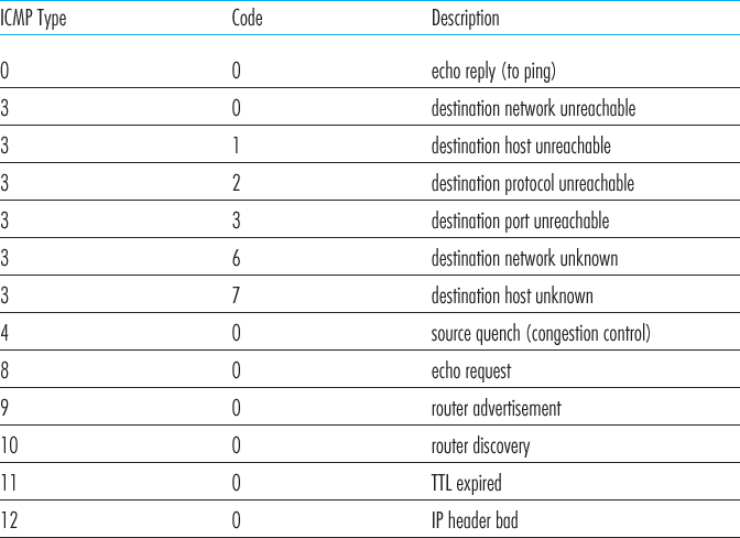
The Internet Control Message Protocol (ICMP), specified in [RFC 792], is used by hosts and routers to communicate network-layer information to each other. The most typical use of ICMP is for error reporting. For example, when running an HTTP session, you may have encountered an error message such as “Destination network unreachable.” This message had its origins in ICMP. At some point, an IP router was unable to find a path to the host specified in your HTTP request. That router created and sent an ICMP message to your host indicating the error.
ICMP is often considered part of IP, but architecturally it lies just above IP, as ICMP messages are carried inside IP datagrams. That is, ICMP messages are carried as IP payload, just as TCP or UDP segments are carried as IP payload. Similarly, when a host receives an IP datagram with ICMP specified as the upper-layer protocol (an upper-layer protocol number of 1), it demultiplexes the datagram’s contents to ICMP, just as it would demultiplex a datagram’s content to TCP or UDP.
ICMP messages have a type and a code field, and contain the header and the first 8 bytes of the IP datagram that caused the ICMP message to be generated in the first place (so that the sender can determine the datagram that caused the error).
The well-known ping program sends an ICMP type 8 code 0 message to the specified host. The destination host, seeing the echo request, sends back a type 0 code 0 ICMP echo reply. Most TCP/IP implementations support the ping server directly in the operating system; that is, the server is not a process.
5.7 Network Management and SNMP
5.7.1 The Network Management Framework
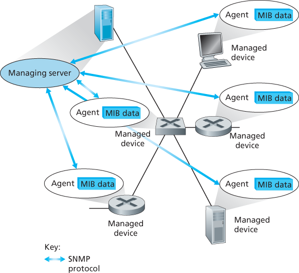
The key components of network management:
- The managing server is an application, typically with a human in the loop, running in a centralized network management station in the network operations center (NOC). The managing server is the locus of activity for network management; it controls the collection, processing, analysis, and/or display of network management information. It is here that actions are initiated to control network behavior and here that the human network administrator interacts with the network’s devices.
- A managed device is a piece of network equipment (including its software) that resides on a managed network. A managed device might be a host, router, switch, middlebox, modem, thermometer, or other network-connected device. There may be several so-called managed objects within a managed device. These managed objects are the actual pieces of hardware within the managed device (for example, a network interface card is but one component of a host or router), and configuration parameters for these hardware and software components (for example, an intra-AS routing protocol such as OSPF).
- Each managed object within a managed device associated information that is collected into a Management Information Base (MIB). A MIB object might be a counter, such as the number of IP datagrams discarded at a router due to errors in an IP datagram header, or the number of UDP segments received at a host; descriptive information such as the version of the software running on a DNS server; status information such as whether a particular device is functioning correctly; or protocol-specific information such as a routing path to a destination. MIB objects are specified in a data description language known as SMI (Structure of Management Information) [RFC 2578; RFC 2579; RFC 2580]. A formal definition language is used to ensure that the syntax and semantics of the network management data are well defined and unambiguous. Related MIB objects are gathered into MIB modules. As of mid-2015, there were nearly 400 MIB modules defined by RFCs, and a much larger number of vendor-specific (private) MIB modules.
- Also resident in each managed device is a network management agent, a process running in the managed device that communicates with the managing server, taking local actions at the managed device under the command and control of the managing server. The network management agent is similar to the routing agent.
- The final component of a network management framework is the network management protocol. The protocol runs between the managing server and the managed devices, allowing the managing server to query the status of managed devices and indirectly take actions at these devices via its agents. Agents can use the network management protocol to inform the managing server of exceptional events (for example, component failures or violation of performance thresholds). It’s important to note that the network management protocol does not itself manage the network. Instead, it provides capabilities that a network administrator can use to manage (“monitor, test, poll, configure, analyze, evaluate, and control”) the network.
5.7.2 The Simple Network Management Protocol (SNMP)
The Simple Network Management Protocol version 2 (SNMPv2) [RFC 3416] is an application-layer protocol used to convey network-management control and information messages between a managing server and an agent executing on behalf of that managing server.
SNMPv2 defines seven types of messages, known generically as protocol data units—PDUs:
- The
GetRequest,GetNextRequest,andGetBulkRequestPDUs are all sent from a managing server to an agent to request the value of one or more MIB objects at the agent’s managed device. The MIB objects whose values are being requested are specified in the variable binding portion of the PDU.GetRequest,GetNextRequest, andGetBulkRequestdiffer in the granularity of their data requests.GetRequestcan request an arbitrary set of MIB values; multipleGetNextRequests can be used to sequence through a list or table of MIB objects;GetBulkRequestallows a large block of data to be returned, avoiding the overhead incurred if multipleGetRequestorGetNextRequestmessages were to be sent. In all three cases, the agent responds with aResponse PDUcontaining the object identifiers and their associated values. - The
SetRequestPDU is used by a managing server to set the value of one or more MIB objects in a managed device. An agent replies with aResponsePDU with the “noError” error status to confirm that the value has indeed been set. - The
InformRequestPDU is used by a managing server to notify another managing server of MIB information that is remote to the receiving server. - The
Response PDUis typically sent from a managed device to the managing server in response to a request message from that server, returning the requested information. - The final type of SNMPv2 PDU is the trap message. Trap messages are generated asynchronously; that is, they are not generated in response to a received request but rather in response to an event for which the managing server requires notification. RFC 3418 defines well-known trap types that include a cold or warm start by a device, a link going up or down, the loss of a neighbor, or an authentication failure event. A received trap request has no required response from a managing server.
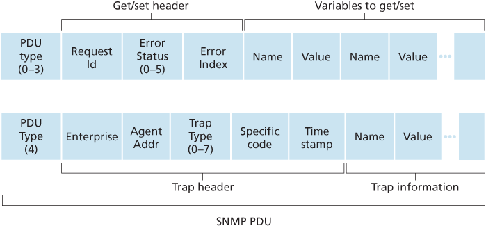
Given the request-response nature of SNMP, it is worth noting here that although SNMP PDUs can be carried via many different transport protocols, the SNMP PDU is typically carried in the payload of a UDP datagram.
SNMP has evolved through three versions. The designers of SNMPv3 have said that “SNMPv3 can be thought of as SNMPv2 with additional security and administration capabilities” [RFC 3410].