
Chapter 4 The Network Layer: Data Plane
4.1 Overview of Network Layer
4.1.1 Forwarding and Routing: The Data and Control Planes
Two important network-layer functions can be identified:
- Forwarding. When a packet arrives at a router’s input link, the router must move the packet to the appropriate output link.
- Routing. The network layer must determine the route or path taken by packets as they flow from a sender to a receiver. The algorithms that calculate these paths are referred to as routing algorithms.
A key element in every network router is its forwarding table.
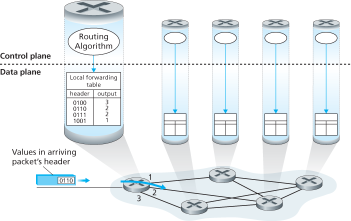
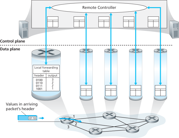
Control Plane: The SDN Approach
4.1.2 Network Service Model
A network layer could provide—there are countless variations possible.
The Internet’s network layer provides a single service, known as best-effort service. With best-effort service, packets are neither guaranteed to be received in the order in which they were sent, nor is their eventual delivery even guaranteed. There is no guarantee on the end-to-end delay nor is there a minimal bandwidth guarantee. It might appear that best-effort service is a euphemism for _no service at all_—a network that delivered no packets to the destination would satisfy the definition of best-effort delivery service!
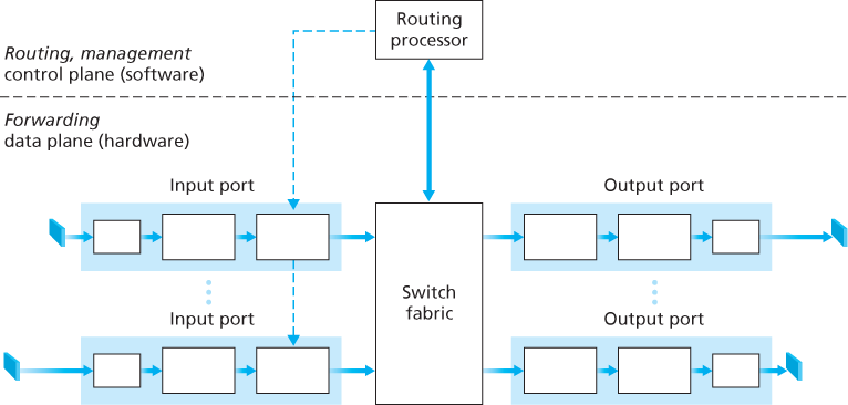
4.2 What’s Inside a Router?
Four router components can be identified:
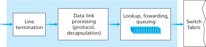
- Input ports. An input port performs several key functions. It performs the physical layer function of terminating an incoming physical link at a router. An input port also performs link-layer functions needed to interoperate with the link layer at the other side of the incoming link; this is represented by the middle boxes in the input and output ports. Perhaps most crucially, a lookup function is also performed at the input port. It is here that the forwarding table is consulted to determine the router output port to which an arriving packet will be forwarded via the switching fabric. Control packets (for example, packets carrying routing protocol information) are forwarded from an input port to the routing processor. Note that the term “port” here—referring to the physical input and output router interfaces.
- Switching fabric. The switching fabric connects the router’s input ports to its output ports. This switching fabric is completely contained within the router—a network inside of a network router!
- Output ports. An output port stores packets received from the switching fabric and transmits these packets on the outgoing link by performing the necessary link-layer and physical-layer functions. When a link is bidirectional (that is, carries traffic in both directions), an output port will typically be paired with the input port for that link on the same line card.
- Routing processor. The routing processor performs control-plane functions. In traditional routers, it executes the routing protocols, maintains routing tables and attached link state information, and computes the forwarding table for the router. In SDN routers, the routing processor is responsible for communicating with the remote controller in order to (among other activities) receive forwarding table entries computed by the remote controller, and install these entries in the router’s input ports. The routing processor also performs the network management functions.
4.2.1 Input Port Processing and Destination-Based Forwarding
The forwarding table is copied from the routing processor to the line cards over a separate bus (e.g., a PCI bus) indicated by the dashed line from the routing processor to the input line cards. With such a shadow copy at each line card, forwarding decisions can be made locally, at each input port, without invoking the centralized routing processor on a per-packet basis and thus avoiding a centralized processing bottleneck.
4.2.2 Switching
Switching can be accomplished in a number of ways.
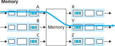
- Switching via memory. The simplest, earliest routers were traditional computers, with switching between input and output ports being done under direct control of the CPU (routing processor). Input and output ports functioned as traditional I/O devices in a traditional operating system. An input port with an arriving packet first signaled the routing processor via an interrupt. The packet was then copied from the input port into processor memory. The routing processor then extracted the destination address from the header, looked up the appropriate output port in the forwarding table, and copied the packet to the output port’s buffers. In this scenario, if the memory bandwidth is such that a maximum of B packets per second can be written into, or read from, memory, then the overall forwarding throughput (the total rate at which packets are transferred from input ports to output ports) must be less than B/2. Note also that two packets cannot be forwarded at the same time, even if they have different destination ports, since only one memory read/write can be done at a time over the shared system bus.
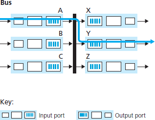
- Switching via a bus. In this approach, an input port transfers a packet directly to the output port over a shared bus, without intervention by the routing processor. This is typically done by having the input port pre-pend a switch-internal label (header) to the packet indicating the local output port to which this packet is being transferred and transmitting the packet onto the bus. All output ports receive the packet, but only the port that matches the label will keep the packet. The label is then removed at the output port, as this label is only used within the switch to cross the bus. If multiple packets arrive to the router at the same time, each at a different input port, all but one must wait since only one packet can cross the bus at a time. Because every packet must cross the single bus, the switching speed of the router is limited to the bus speed.
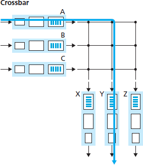
- Switching via an interconnection network. A crossbar switch is an interconnection network consisting of 2N buses that connect N input ports to N output ports. Each vertical bus intersects each horizontal bus at a crosspoint, which can be opened or closed at any time by the switch fabric controller (whose logic is part of the switching fabric itself).
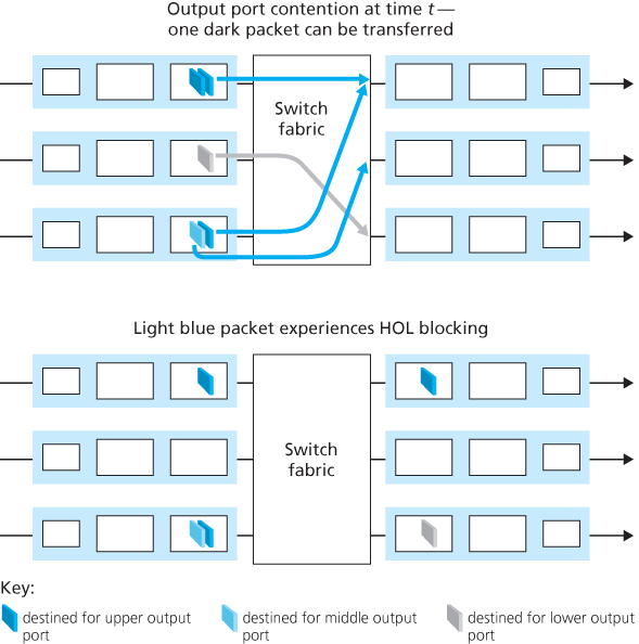
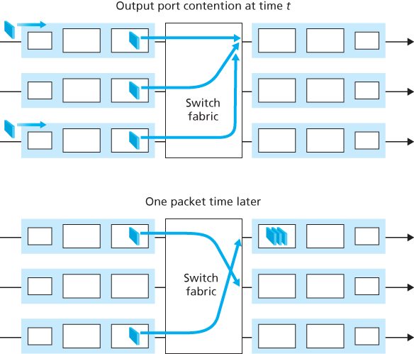
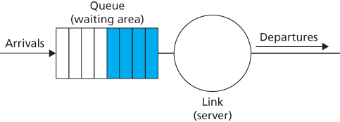
4.2.4 Where Does Queuing Occur?
Packet queues may form at both the input ports and the output ports. Since as these queues grow large, the router’s memory can eventually be exhausted and packet loss will occur when no memory is available to store arriving packets.
Input Queueing
Output Queueing
4.2.5 Packet Scheduling
First-in-First-Out (FIFO)
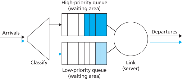
Priority Queuing
Under priority queuing, packets arriving at the output link are classified into priority classes upon arrival at the queue.
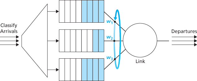
Round Robin and Weighted Fair Queuing (WFQ)
Under the round robin queuing discipline, packets are sorted into classes as with priority queuing. However, rather than there being a strict service priority among classes, a round robin scheduler alternates service among the classes.
4.3 The Internet Protocol (IP): IPv4, Addressing, IPv6, and More
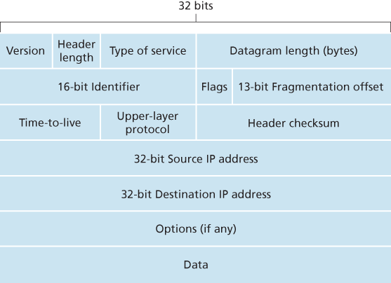
4.3.1 IPv4 Datagram Format
The key fields in the IPv4 datagram are the following:
- Version number. These 4 bits specify the IP protocol version of the datagram. By looking at the version number, the router can determine how to interpret the remainder of the IP datagram.
- Header length. Because an IPv4 datagram can contain a variable number of options (which are included in the IPv4 datagram header), these 4 bits are needed to determine where in the IP datagram the payload (e.g., the transport-layer segment being encapsulated in this datagram) actually begins. Most IP datagrams do not contain options, so the typical IP datagram has a 20-byte header.
- Type of service. The type of service (TOS) bits were included in the IPv4 header to allow different types of IP datagrams to be distinguished from each other. For example, it might be useful to distinguish real-time datagrams (such as those used by an IP telephony application) from non-real-time traffic (for example, FTP). The specific level of service to be provided is a policy issue determined and configured by the network administrator for that router.
- Datagram length. This is the total length of the IP datagram (header plus data), measured in bytes. Since this field is 16 bits long, the theoretical maximum size of the IP datagram is 65,535 bytes. However, datagrams are rarely larger than 1,500 bytes, which allows an IP datagram to fit in the payload field of a maximally sized Ethernet frame.
- Identifier, flags, fragmentation offset. These three fields have to do with so-called IP fragmentation, a topic we will consider shortly. Interestingly, the new version of IP, IPv6, does not allow for fragmentation.
- Time-to-live. The time-to-live (TTL) field is included to ensure that datagrams do not circulate forever (due to, for example, a long-lived routing loop) in the network. This field is decremented by one each time the datagram is processed by a router. If the TTL field reaches 0, a router must drop that datagram.
- Protocol. This field is typically used only when an IP datagram reaches its final destination. The value of this field indicates the specific transport-layer protocol to which the data portion of this IP datagram should be passed. For example, a value of 6 indicates that the data portion is passed to TCP, while a value of 17 indicates that the data is passed to UDP. Note that the protocol number in the IP datagram has a role that is analogous to the role of the port number field in the transport-layer segment. The protocol number is the glue that binds the network and transport layers together, whereas the port number is the glue that binds the transport and application layers together.
- Header checksum. The header checksum aids a router in detecting bit errors in a received IP datagram. The header checksum is computed by treating each 2 bytes in the header as a number and summing these numbers using 1s complement arithmetic. Note that the checksum must be recomputed and stored again at each router, since the TTL field, and possibly the options field as well, will change.
- Source and destination IP addresses.
- Options. The options fields allow an IP header to be extended.
- Data (payload). In most circumstances, the data field of the IP datagram contains the transport-layer segment (TCP or UDP) to be delivered to the destination. However, the data field can carry other types of data, such as ICMP messages.
4.3.2 IPv4 Datagram Fragmentation
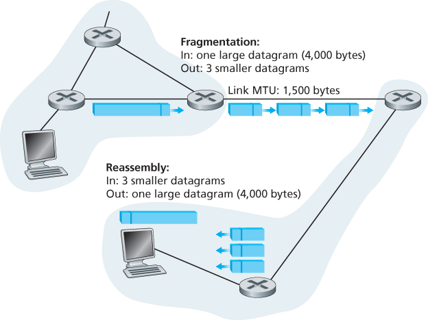
Not all link-layer protocols can carry network-layer packets of the same size. Some protocols can carry big datagrams, whereas other protocols can carry only little datagrams. The maximum amount of data that a link-layer frame can carry is called the maximum transmission unit (MTU). Because each IP datagram is encapsulated within the link-layer frame for transport from one router to the next router, the MTU of the link-layer protocol places a hard limit on the length of an IP datagram. Having a hard limit on the size of an IP datagram is not much of a problem. What is a problem is that each of the links along the route between sender and destination can use different link-layer protocols, and each of these protocols can have different MTUs.
Suppose you receive an IP datagram from one link. You check your forwarding table to determine the outgoing link, and this outgoing link has an MTU that is smaller than the length of the IP datagram. Time to panic—how are you going to squeeze this oversized IP datagram into the payload field of the link-layer frame? The solution is to fragment the payload in the IP datagram into two or more smaller IP datagrams, encapsulate each of these smaller IP datagrams in a separate link-layer frame; and send these frames over the outgoing link. Each of these smaller datagrams is referred to as a fragment.
Fragments need to be reassembled before they reach the transport layer at the destination. Indeed, both TCP and UDP are expecting to receive complete, unfragmented segments from the network layer. The designers of IPv4 felt that reassembling datagrams in the routers would introduce significant complication into the protocol and put a damper on router performance. (If you were a router, would you want to be reassembling fragments on top of everything else you had to do?) Sticking to the principle of keeping the network core simple, the designers of IPv4 decided to put the job of datagram reassembly in the end systems rather than in network routers.
4.3.3 IPv4 Addressing
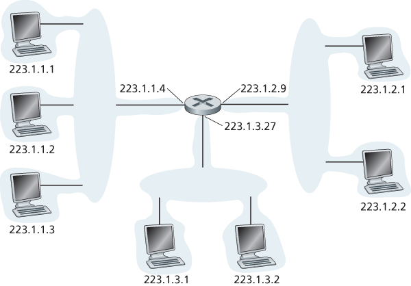
The boundary between the host and the physical link is called an interface.
Each IP address is 32 bits long (equivalently, 4 bytes), and there are thus a total of
Each interface on every host and router in the global Internet must have an IP address that is globally unique (except for interfaces behind NATs). A portion of an interface’s IP address will be determined by the subnet to which it is connected.
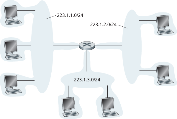
A subnet is also called an IP network or simply a network in the Internet literature. IP addressing assigns an address to this subnet: 223.1.1.0/24, where the /24 (“slash-24”) notation, sometimes known as a subnet mask, indicates that the leftmost 24 bits of the 32-bit quantity define the subnet address.
The IP definition of a subnet is not restricted to Ethernet segments that connect multiple hosts to a router interface.
The Internet’s address assignment strategy is known as Classless Interdomain Routing (CIDR—pronounced cider) [RFC 4632]. CIDR generalizes the notion of subnet addressing. As with subnet addressing, the 32-bit IP address is divided into two parts and again has the dotted-decimal form a.b.c.d/x, where x indicates the number of bits in the first part of the address.
The x most significant bits of an address of the form a.b.c.d/x constitute the network portion of the IP address, and are often referred to as the prefix (or network prefix) of the address. An organization is typically assigned a block of contiguous addresses, that is, a range of addresses with a common prefix.
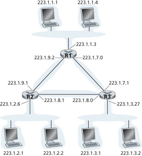
That is, when a router outside the organization forwards a datagram whose destination address is inside the organization, only the leading x bits of the address need be considered.
The remaining 32-x bits of an address can be thought of as distinguishing among the devices within the organization, all of which have the same network prefix. These are the bits that will be considered when forwarding packets at routers within the organization.
Before CIDR was adopted, the network portions of an IP address were constrained to be 8, 16, or 24 bits in length, an addressing scheme known as classful addressing, since subnets with 8-, 16-, and 24-bit subnet addresses were known as class A, B, and C networks, respectively. The requirement that the subnet portion of an IP address be exactly 1, 2, or 3 bytes long turned out to be problematic for supporting the rapidly growing number of organizations with small and medium-sized subnets. A class C (/24) subnet could accommodate only up to
Obtaining a Host Address: The Dynamic Host Configuration Protocol
Host addresses can also be configured manually, but typically this is done using the Dynamic Host Configuration Protocol (DHCP) [RFC 2131]. DHCP allows a host to obtain (be allocated) an IP address automatically. A network administrator can configure DHCP so that a given host receives the same IP address each time it connects to the network, or a host may be assigned a temporary IP address that will be different each time the host connects to the network. In addition to host IP address assignment, DHCP also allows a host to learn additional information, such as its subnet mask, the address of its first-hop router (often called the default gateway), and the address of its local DNS server.
Because of DHCP’s ability to automate the network-related aspects of connecting a host into a network, it is often referred to as a plug-and-play or zeroconf (zero-configuration) protocol.
For a newly arriving host, the DHCP protocol is a four-step process.
- DHCP server discovery. The first task of a newly arriving host is to find a DHCP server with which to interact. This is done using a DHCP discover message, which a client sends within a UDP packet to port 67. The UDP packet is encapsulated in an IP datagram. But to whom should this datagram be sent? The host doesn’t even know the IP address of the network to which it is attaching, much less the address of a DHCP server for this network. Given this, the DHCP client creates an IP datagram containing its DHCP discover message along with the broadcast destination IP address of 255.255.255.255 and a “this host” source IP address of 0.0.0.0. The DHCP client passes the IP datagram to the link layer, which then broadcasts this frame to all nodes attached to the subnet.
- DHCP server offer(s). A DHCP server receiving a DHCP discover message responds to the client with a DHCP offer message that is broadcast to all nodes on the subnet, again using the IP broadcast address of 255.255.255.255. (You might want to think about why this server reply must also be broadcast). Since several DHCP servers can be present on the subnet, the client may find itself in the enviable position of being able to choose from among several offers. Each server offer message contains the transaction ID of the received discover message, the proposed IP address for the client, the network mask, and an IP address lease time—the amount of time for which the IP address will be valid. It is common for the server to set the lease time to several hours or days [Droms 2002].
- DHCP request. The newly arriving client will choose from among one or more server offers and respond to its selected offer with a DHCP request message, echoing back the configuration parameters.
- DHCP ACK. The server responds to the DHCP request message with a DHCP ACK message, confirming the requested parameters.
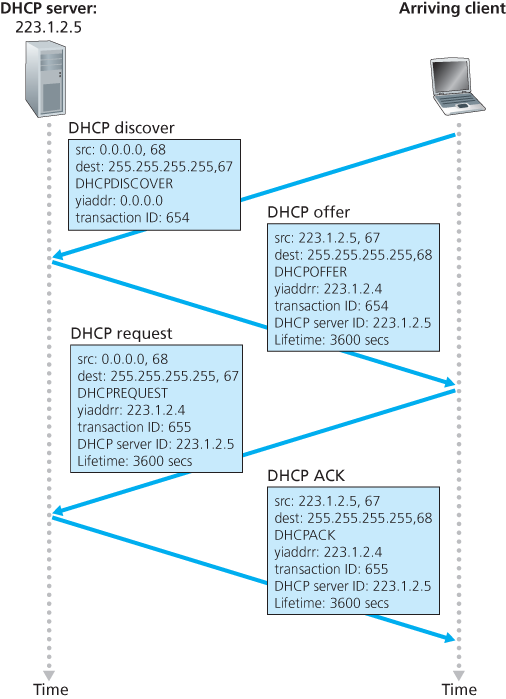
Once the client receives the DHCP ACK, the interaction is complete and the client can use the DHCP-allocated IP address for the lease duration. Since a client may want to use its address beyond the lease’s expiration, DHCP also provides a mechanism that allows a client to renew its lease on an IP address.
4.3.4 Network Address Translation (NAT)
The address space 10.0.0.0/8 is one of three portions of the IP address space that is reserved in [RFC 1918] for a private network or a realm with private addresses. A realm with private addresses refers to a network whose addresses only have meaning to devices within that network.
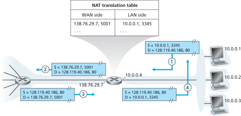
The NAT-enabled router does not look like a router to the outside world. Instead the NAT router behaves to the outside world as a single device with a single IP address.
If all datagrams arriving at the NAT router from the WAN have the same destination IP address (specifically, that of the WAN-side interface of the NAT router), then how does the router know the internal host to which it should forward a given datagram? The trick is to use a NAT translation table at the NAT router, and to include port numbers as well as IP addresses in the table entries.
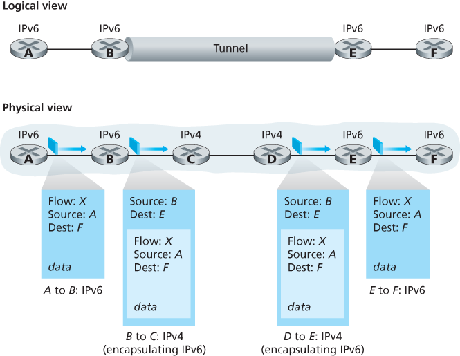
4.3.5 IPv6
IPv6 Datagram Format
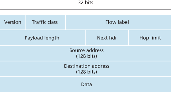
The most important changes introduced in IPv6 are evident in the datagram format:
- Expanded addressing capabilities. IPv6 increases the size of the IP address from 32 to 128 bits. This ensures that the world won’t run out of IP addresses. Now, every grain of sand on the planet can be IP-addressable. In addition to unicast and multicast addresses, IPv6 has introduced a new type of address, called an anycast address, that allows a datagram to be delivered to any one of a group of hosts. This feature could be used, for example, to send an HTTP GET to the nearest of a number of mirror sites that contain a given document.
- A streamlined 40-byte header. As discussed below, a number of IPv4 fields have been dropped or made optional. The resulting 40-byte fixed-length header allows for faster processing of the IP datagram by a router. A new encoding of options allows for more flexible options processing.
- Flow labeling. IPv6 has an elusive definition of a flow. RFC 2460 states that this allows “labeling of packets belonging to particular flows for which the sender requests special handling, such as a non-default quality of service or real-time service.” For example, audio and video transmission might likely be treated as a flow. On the other hand, the more traditional applications, such as file transfer and e-mail, might not be treated as flows. It is possible that the traffic carried by a high-priority user (for example, someone paying for better service for their traffic) might also be treated as a flow. What is clear, however, is that the designers of IPv6 foresaw the eventual need to be able to differentiate among the flows, even if the exact meaning of a flow had yet to be determined.
The following fields are defined in IPv6:
- Version. This 4-bit field identifies the IP version number. Not surprisingly, IPv6 carries a value of 6 in this field. Note that putting a 4 in this field does not create a valid IPv4 datagram.
- Traffic class. The 8-bit traffic class field, like the TOS field in IPv4, can be used to give priority to certain datagrams within a flow, or it can be used to give priority to datagrams from certain applications (for example, voice-over-IP) over datagrams from other applications (for example, SMTP e-mail).
- Flow label. This 20-bit field is used to identify a flow of datagrams.
- Payload length. This 16-bit value is treated as an unsigned integer giving the number of bytes in the IPv6 datagram following the fixed-length, 40-byte datagram header.
- Next header. This field identifies the protocol to which the contents (data field) of this datagram will be delivered (for example, to TCP or UDP). The field uses the same values as the protocol field in the IPv4 header.
- Hop limit. The contents of this field are decremented by one by each router that forwards the datagram. If the hop limit count reaches zero, the datagram is discarded.
- Source and destination addresses. The various formats of the IPv6 128-bit address are described in RFC 4291.
- Data. This is the payload portion of the IPv6 datagram. When the datagram reaches its destination, the payload will be removed from the IP datagram and passed on to the protocol specified in the next header field.
Several fields appearing in the IPv4 datagram are no longer present in the IPv6 datagram:
- Fragmentation/reassembly. IPv6 does not allow for fragmentation and reassembly at intermediate routers; these operations can be performed only by the source and destination. If an IPv6 datagram received by a router is too large to be forwarded over the outgoing link, the router simply drops the datagram and sends a “Packet Too Big” ICMP error message back to the sender. The sender can then resend the data, using a smaller IP datagram size. Fragmentation and reassembly is a time-consuming operation; removing this functionality from the routers and placing it squarely in the end systems considerably speeds up IP forwarding within the network.
- Header checksum. Because the transport-layer (for example, TCP and UDP) and link-layer (for example, Ethernet) protocols in the Internet layers perform checksumming, the designers of IP probably felt that this functionality was sufficiently redundant in the network layer that it could be removed. Once again, fast processing of IP packets was a central concern. Since the IPv4 header contains a TTL field (similar to the hop limit field in IPv6), the IPv4 header checksum needed to be recomputed at every router. As with fragmentation and reassembly, this too was a costly operation in IPv4.
- Options. An options field is no longer a part of the standard IP header. However, it has not gone away. Instead, the options field is one of the possible next headers pointed to from within the IPv6 header. That is, just as TCP or UDP protocol headers can be the next header within an IP packet, so too can an options field. The removal of the options field results in a fixed-length, 40-byte IP header.
Transitioning from IPv4 to IPv6
4.4 Generalized Forwarding and SDN
In generalized forwarding, a match-plus-action table generalizes the notion of the destination-based forwarding table.
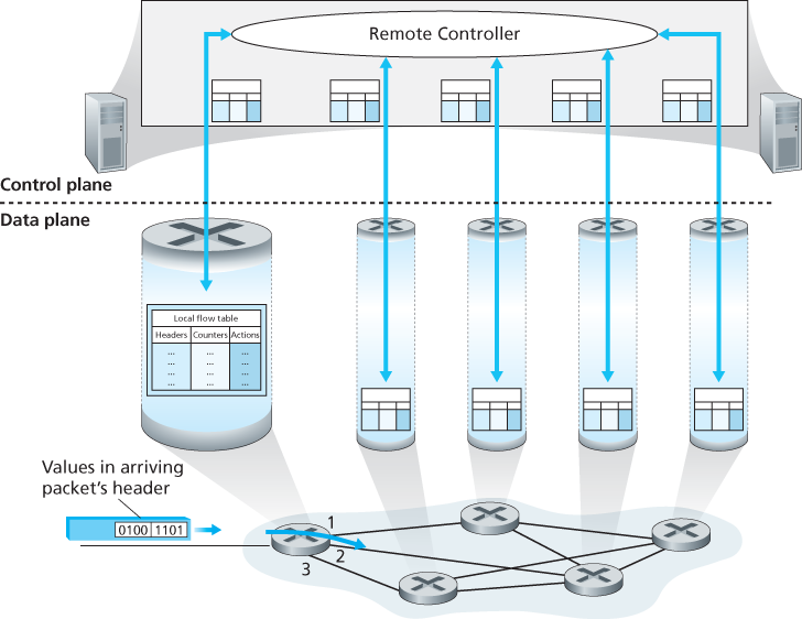
Our following discussion of generalized forwarding will be based on OpenFlow [McKeown 2008, OpenFlow 2009, Casado 2014, Tourrilhes 2014]—a highly visible and successful standard that has pioneered the notion of the match-plus-action forwarding abstraction and controllers, as well as the SDN revolution more generally [Feamster 2013].
Each entry in the match-plus-action forwarding table, known as a flow table in OpenFlow, includes:
- A set of header field values to which an incoming packet will be matched. As in the case of destination-based forwarding, hardware-based matching is most rapidly performed in TCAM memory, with more than a million destination address entries being possible [Bosshart 2013]. A packet that matches no flow table entry can be dropped or sent to the remote controller for more processing. In practice, a flow table may be implemented by multiple flow tables for performance or cost reasons [Bosshart 2013], but we’ll focus here on the abstraction of a single flow table.
- A set of counters that are updated as packets are matched to flow table entries. These counters might include the number of packets that have been matched by that table entry, and the time since the table entry was last updated.
- A set of actions to be taken when a packet matches a flow table entry. These actions might be to forward the packet to a given output port, to drop the packet, makes copies of the packet and sent them to multiple output ports, and/or to rewrite selected header fields.
4.4.1 Match
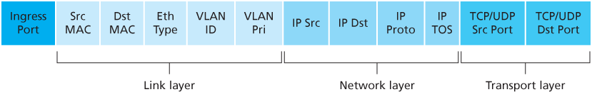
The ingress port refers to the input port at the packet switch on which a packet is received.
Flow table entries may also have wildcards. For example, an IP address of 128.119.. in a flow table will match the corresponding address field of any datagram that has 128.119 as the first 16 bits of its address. Each flow table entry also has an associated priority. If a packet matches multiple flow table entries, the selected match and corresponding action will be that of the highest priority entry with which the packet matches.
4.4.2 Action
Among the most important possible actions are:
- Forwarding. An incoming packet may be forwarded to a particular physical output port, broadcast over all ports (except the port on which it arrived) or multicast over a selected set of ports. The packet may be encapsulated and sent to the remote controller for this device. That controller then may (or may not) take some action on that packet, including installing new flow table entries, and may return the packet to the device for forwarding under the updated set of flow table rules.
- Dropping. A flow table entry with no action indicates that a matched packet should be dropped.
- Modify-field. The values in ten packet header fields.