
Chapter 3 Transport Layer
3.1 Introduction and Transport-Layer Services
A transport-layer protocol provides for logical communication between application processes running on different hosts.
Transport-layer protocols are implemented in the end systems but not in network routers. On the sending side, the transport layer converts the application-layer messages it receives from a sending application process into transport-layer packets, known as transport-layer segments in Internet terminology. This is done by (possibly) breaking the application messages into smaller chunks and adding a transport-layer header to each chunk to create the transport-layer segment. The transport layer then passes the segment to the network layer at the sending end system, where the segment is encapsulated within a network-layer packet (a datagram) and sent to the destination. It’s important to note that network routers act only on the network-layer fields of the datagram; that is, they do not examine the fields of the transport-layer segment encapsulated with the datagram. On the receiving side, the network layer extracts the transport-layer segment from the datagram and passes the segment up to the transport layer. The transport layer then processes the received segment, making the data in the segment available to the receiving application.
3.1.1 Relationship Between Transport and Network Layers
The services that a transport protocol can provide are often constrained by the service model of the underlying network-layer protocol. If the network-layer protocol cannot provide delay or bandwidth guarantees for transport-layer segments sent between hosts, then the transport-layer protocol cannot provide delay or bandwidth guarantees for application messages sent between processes.
Nevertheless, certain services can be offered by a transport protocol even when the underlying network protocol doesn’t offer the corresponding service at the network layer. For example, a transport protocol can offer reliable data transfer service to an application even when the underlying network protocol is unreliable, that is, even when the network protocol loses, garbles, or duplicates packets.
3.2 Multiplexing and Demultiplexing
The transport layer in the receiving host does not actually deliver data directly to a process, but instead to an intermediary socket. Because at any given time there can be more than one socket in the receiving host, each socket has a unique identifier. The format of the identifier depends on whether the socket is a UDP or a TCP socket.
This job of delivering the data in a transport-layer segment to the correct socket is called demultiplexing. The job of gathering data chunks at the source host from different sockets, encapsulating each data chunk with header information (that will later be used in demultiplexing) to create segments, and passing the segments to the network layer is called multiplexing.
The transport layer could implement the demultiplexing service: Each socket in the host could be assigned a port number, and when a segment arrives at the host, the transport layer examines the destination port number in the segment and directs the segment to the corresponding socket. The segment’s data then passes through the socket into the attached process.
Connectionless Multiplexing and Demultiplexing
It is important to note that a UDP socket is fully identified by a two-tuple consisting of a destination IP address and a destination port number. As a consequence, if two UDP segments have different source IP addresses and/or source port numbers, but have the same destination IP address and destination port number, then the two segments will be directed to the same destination process via the same destination socket.
Connection-Oriented Multiplexing and Demultiplexing
One subtle difference between a TCP socket and a UDP socket is that a TCP socket is identified by a four-tuple: (source IP address, source port number, destination IP address, destination port number). Thus, when a TCP segment arrives from the network to a host, the host uses all four values to direct (demultiplex) the segment to the appropriate socket.
In particular, and in contrast with UDP, two arriving TCP segments with different source IP addresses or source port numbers will (with the exception of a TCP segment carrying the original connection-establishment request) be directed to two different sockets.
3.3 Connectionless Transport: UDP
UDP, defined in [RFC 768], does just about as little as a transport protocol can do. Aside from the multiplexing/demultiplexing function and some light error checking, it adds nothing to IP. In fact, if the application developer chooses UDP instead of TCP, then the application is almost directly talking with IP.
DNS is an example of an application-layer protocol that typically uses UDP. When the DNS application in a host wants to make a query, it constructs a DNS query message and passes the message to UDP. Without performing any handshaking with the UDP entity running on the destination end system, the host-side UDP adds header fields to the message and passes the resulting segment to the network layer. The network layer encapsulates the UDP segment into a datagram and sends the datagram to a name server. The DNS application at the querying host then waits for a reply to its query. If it doesn’t receive a reply (possibly because the underlying network lost the query or the reply), it might try resending the query, try sending the query to another name server, or inform the invoking application that it can’t get a reply.
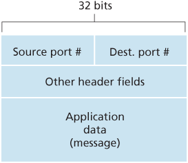
3.3.1 UDP Segment Structure
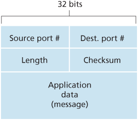
3.3.2 UDP Checksum
UDP at the sender side performs the 1s complement of the sum of all the 16-bit words in the segment, with any overflow encountered during the sum being wrapped around. This result is put in the checksum field of the UDP segment.
As an example, suppose that we have the following three 16-bit words:
0110011001100000
0101010101010101
1000111100001100
The sum of first two of these 16-bit words is:
0110011001100000
0101010101010101
1011101110110101
Adding the third word to the above sum gives:
1011101110110101
1000111100001100
0100101011000010
Note that this last addition had overflow, which was wrapped around. The 1s complement is obtained by converting all the 0s to 1s and converting all the 1s to 0s. Thus the 1s complement of the sum 0100101011000010 is 1011010100111101, which becomes the checksum. At the receiver, all four 16-bit words are added, including the checksum. If no errors are introduced into the packet, then clearly the sum at the receiver will be 1111111111111111. If one of the bits is a 0, then we know that errors have been introduced into the packet.
Although UDP provides error checking, it does not do anything to recover from an error. Some implementations of UDP simply discard the damaged segment; others pass the damaged segment to the application with a warning.
3.4 Principles of Reliable Data Transfer
3.4.1 Building a Reliable Data Transfer Protocol
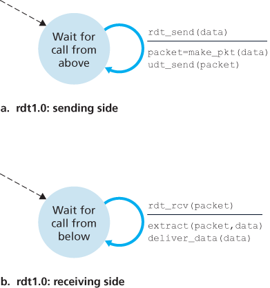
Reliable Data Transfer over a Perfectly Reliable Channel: rdt1.0
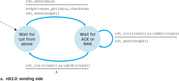
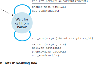
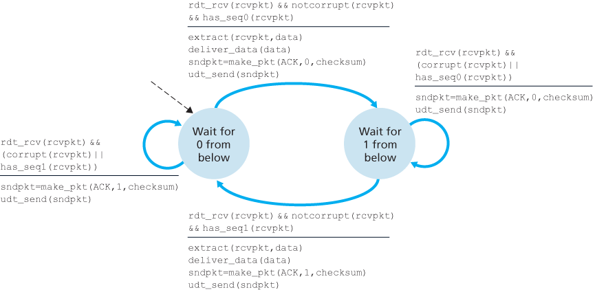
Reliable Data Transfer over a Channel with Bit Errors: rdt2.0
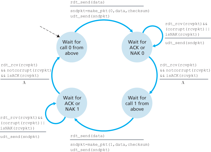
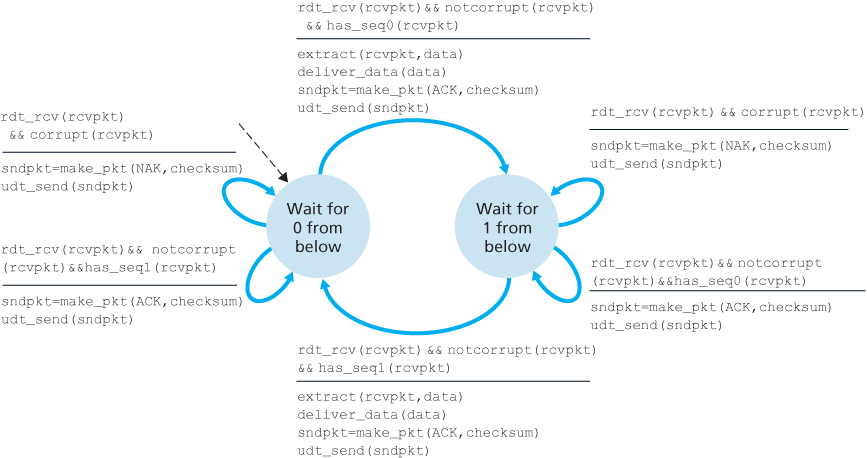
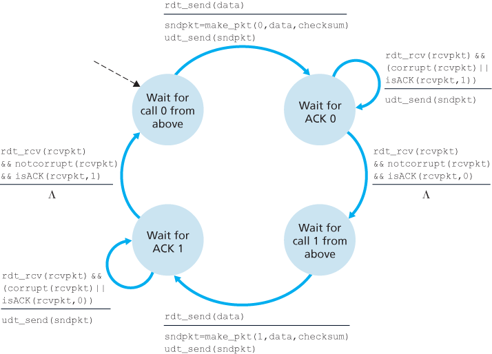
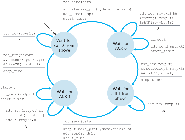
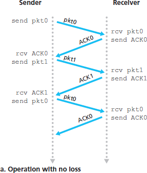
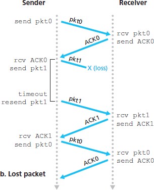
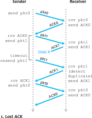
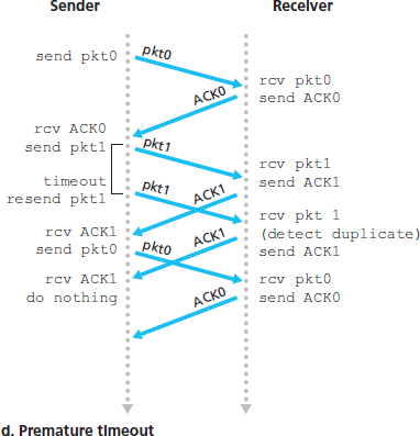
Reliable Data Transfer over a Lossy Channel with Bit Errors: rdt3.0
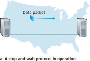
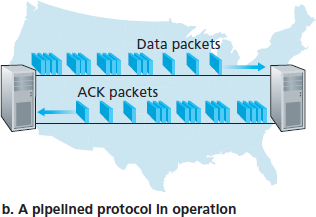
3.4.2 Pipelined Reliable Data Transfer Protocols
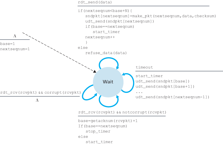
3.4.3 Go-Back-N (GBN)
In a Go-Back-N (GBN) protocol, the sender is allowed to transmit multiple packets (when available) without waiting for an acknowledgment, but is constrained to have no more than some maximum allowable number, N, of unacknowledged packets in the pipeline.
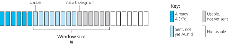
The range of permissible sequence numbers for transmitted but not yet acknowledged packets can be viewed as a window of size N over the range of sequence numbers. As the protocol operates, this window slides forward over the sequence number space. For this reason, N is often referred to as the window size and the GBN protocol itself as a sliding-window protocol.
In practice, a packet’s sequence number is carried in a fixed-length field in the packet header. If k is the number of bits in the packet sequence number field, the range of sequence numbers is thus
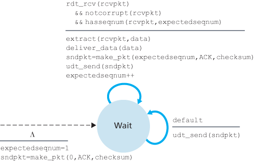
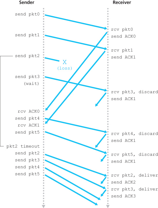
In our GBN protocol, the receiver discards out-of-order packets. Although it may seem silly and wasteful to discard a correctly received (but out-of-order) packet, there is some justification for doing so. Recall that the receiver must deliver data in order to the upper layer. Suppose now that packet n is expected, but packet n + 1 arrives. Because data must be delivered in order, the receiver could buffer (save) packet n + 1 and then deliver this packet to the upper layer after it had later received and delivered packet n. However, if packet n is lost, both it and packet n + 1 will eventually be retransmitted as a result of the GBN retransmission rule at the sender. Thus, the receiver can simply discard packet n + 1. The advantage of this approach is the simplicity of receiver buffering—the receiver need not buffer any out-of-order packets.
The disadvantage of throwing away a correctly received packet is that the subsequent retransmission of that packet might be lost or garbled and thus even more retransmissions would be required.
3.4.4 Selective Repeat (SR)
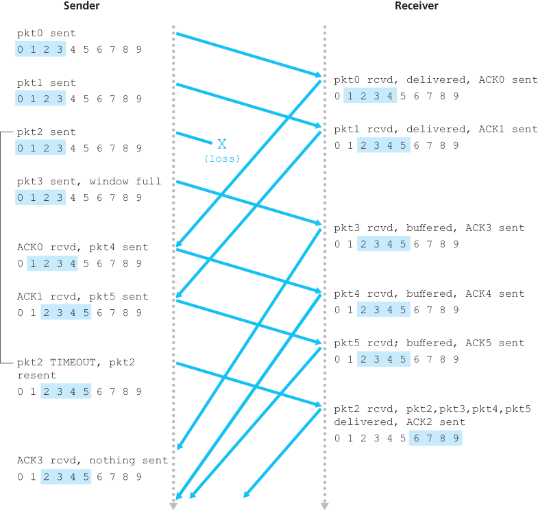
The SR receiver will acknowledge a correctly received packet whether or not it is in order. Out-of-order packets are buffered until any missing packets (that is, packets with lower sequence numbers) are received, at which point a batch of packets can be delivered in order to the upper layer.
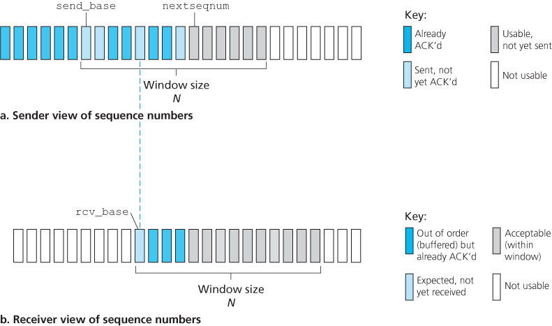
The receiver reacknowledges (rather than ignores) already received packets with certain sequence numbers below the current window base. You should convince yourself that this reacknowledgment is indeed needed. Given the sender and receiver sequence number spaces, for example, if there is no ACK for packet send_base propagating from the receiver to the sender, the sender will eventually retransmit packet send_base, even though it is clear (to us, not the sender!) that the receiver has already received that packet. If the receiver were not to acknowledge this packet, the sender’s window would never move forward! This example illustrates an important aspect of SR protocols (and many other protocols as well). The sender and receiver will not always have an identical view of what has been received correctly and what has not. For SR protocols, this means that the sender and receiver windows will not always coincide.
The lack of synchronization between sender and receiver windows has important consequences when we are faced with the reality of a finite range of sequence numbers. Consider what could happen, for example, with a finite range of four packet sequence numbers, 0, 1, 2, 3, and a window size of three. Suppose packets 0 through 2 are transmitted and correctly received and acknowledged at the receiver. At this point, the receiver’s window is over the fourth, fifth, and sixth packets, which have sequence numbers 3, 0, and 1, respectively. Now consider two scenarios.
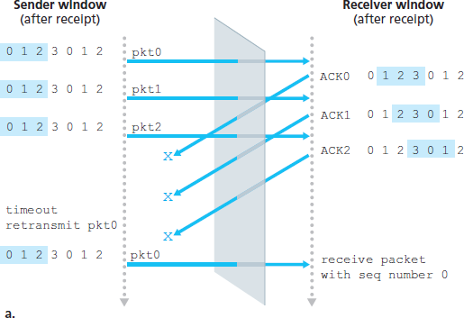
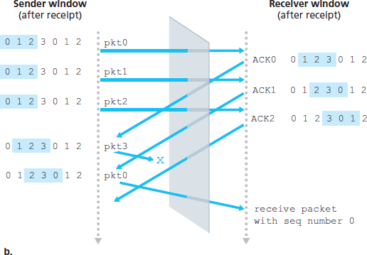
There is no way of distinguishing the retransmission of the first packet from an original transmission of the fifth packet. Clearly, a window size that is 1 less than the size of the sequence number space won’t work. But how small must the window size be? The window size must be less than or equal to half the size of the sequence number space for SR protocols.
3.5 Connection-Oriented Transport: TCP
3.5.1 The TCP Connection
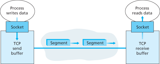
A TCP connection provides a full-duplex service: If there is a TCP connection between Process A on one host and Process B on another host, then application-layer data can flow from Process A to Process B at the same time as application-layer data flows from Process B to Process A. A TCP connection is also always point-to-point, that is, between a single sender and a single receiver. So-called “multicasting”—the transfer of data from one sender to many receivers in a single send operation—is not possible with TCP.
TCP directs this data to the connection’s send buffer, which is one of the buffers that is set aside during the initial three-way handshake. From time to time, TCP will grab chunks of data from the send buffer and pass the data to the network layer.
The maximum amount of data that can be grabbed and placed in a segment is limited by the maximum segment size (MSS). The MSS is typically set by first determining the length of the largest link-layer frame that can be sent by the local sending host (the so-called maximum transmission unit, MTU), and then setting the MSS to ensure that a TCP segment (when encapsulated in an IP datagram) plus the TCP/IP header length (typically 40 bytes) will fit into a single link-layer frame. Both Ethernet and PPP link-layer protocols have an MTU of 1,500 bytes. Thus a typical value of MSS is 1460 bytes. Approaches have also been proposed for discovering the path MTU—the largest link-layer frame that can be sent on all links from source to destination [RFC 1191]—and setting the MSS based on the path MTU value. Note that the MSS is the maximum amount of application-layer data in the segment, not the maximum size of the TCP segment including headers.
3.5.2 TCP Segment Structure
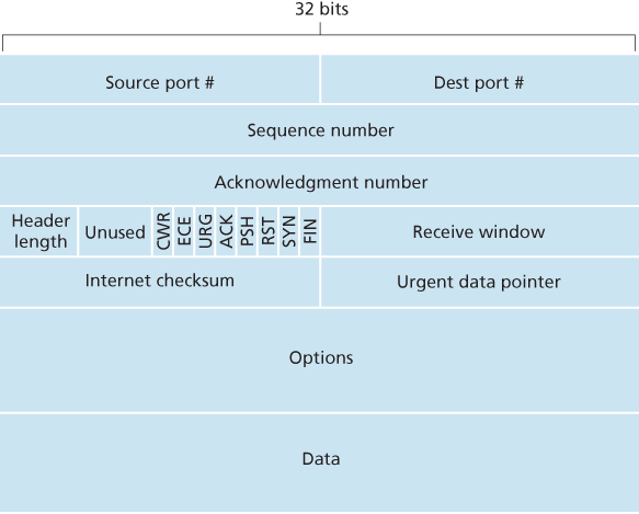
The TCP segment consists of header fields and a data field. The data field contains a chunk of application data. The MSS limits the maximum size of a segment’s data field. When TCP sends a large file, such as an image as part of a Web page, it typically breaks the file into chunks of size MSS (except for the last chunk, which will often be less than the MSS).
A TCP segment header also contains the following fields:
- The 32-bit sequence number field and the 32-bit acknowledgment number field are used by the TCP sender and receiver in implementing a reliable data transfer service, as discussed below.
- The 16-bit receive window field is used for flow control. We will see shortly that it is used to indicate the number of bytes that a receiver is willing to accept.
- The 4-bit header length field specifies the length of the TCP header in 32-bit words. The TCP header can be of variable length due to the TCP options field. Typically, the options field is empty, so that the length of the typical TCP header is 20 bytes.
- The optional and variable-length options field is used when a sender and receiver negotiate the maximum segment size (MSS) or as a window scaling factor for use in high-speed networks. A time-stamping option is also defined.
- The flag field contains 6 bits. The ACK bit is used to indicate that the value carried in the acknowledgment field is valid; that is, the segment contains an acknowledgment for a segment that has been successfully received. The RST, SYN, and FIN bits are used for connection setup and teardown, as we will discuss at the end of this section. The CWR and ECE bits are used in explicit congestion notification. Setting the PSH bit indicates that the receiver should pass the data to the upper layer immediately. Finally, the URG bit is used to indicate that there is data in this segment that the sending-side upper-layer entity has marked as “urgent”. The location of the last byte of this urgent data is indicated by the 16-bit urgent data pointer field. TCP must inform the receiving-side upper-layer entity when urgent data exists and pass it a pointer to the end of the urgent data. In practice, the PSH, URG, and the urgent data pointer are not used.
Sequence Numbers and Acknowledgment Numbers
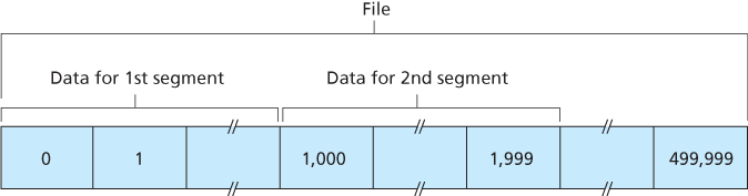
TCP views data as an unstructured, but ordered, stream of bytes. TCP’s use of sequence numbers reflects this view in that sequence numbers are over the stream of transmitted bytes and not over the series of transmitted segments. The sequence number for a segment is therefore the byte-stream number of the first byte in the segment.
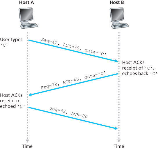
Recall that TCP is full-duplex, so that Host A may be receiving data from Host B while it sends data to Host B (as part of the same TCP connection). Each of the segments that arrive from Host B has a sequence number for the data flowing from B to A. The acknowledgment number that Host A puts in its segment is the sequence number of the next byte Host A is expecting from Host B.
Suppose that Host A has received one segment from Host B containing bytes 0 through 535 and another segment containing bytes 900 through 1,000. For some reason Host A has not yet received bytes 536 through 899. In this example, Host A is still waiting for byte 536 (and beyond) in order to re-create B’s data stream. Thus, A’s next segment to B will contain 536 in the acknowledgment number field. Because TCP only acknowledges bytes up to the first missing byte in the stream, TCP is said to provide cumulative acknowledgments.
We assumed that the initial sequence number was zero. In truth, both sides of a TCP connection randomly choose an initial sequence number. This is done to minimize the possibility that a segment that is still present in the network from an earlier, already-terminated connection between two hosts is mistaken for a valid segment in a later connection between these same two hosts (which also happen to be using the same port numbers as the old connection) [Sunshine 1978].
Telnet: A Case Study for Sequence and Acknowledgment Numbers
3.5.3 Round-Trip Time Estimation and Timeout
Round-trip time (RTT), that is, the time from when a segment is sent until it is acknowledged.
Estimating the Round-Trip Time
The sample RTT, denoted SampleRTT, for a segment is the amount of time between when the segment is sent (that is, passed to IP) and when an acknowledgment for the segment is received. Instead of measuring a SampleRTT for every transmitted segment, most TCP implementations take only one SampleRTT measurement at a time. That is, at any point in time, the SampleRTT is being estimated for only one of the transmitted but currently unacknowledged segments, leading to a new value of SampleRTT approximately once every RTT. Also, TCP never computes a SampleRTT for a segment that has been retransmitted; it only measures SampleRTT for segments that have been transmitted once [Karn 1987].
Obviously, the SampleRTT values will fluctuate from segment to segment due to congestion in the routers and to the varying load on the end systems. Because of this fluctuation, any given SampleRTT value may be atypical. In order to estimate a typical RTT, it is therefore natural to take some sort of average of the SampleRTT values. TCP maintains an average, called EstimatedRTT, of the SampleRTT values. Upon obtaining a new SampleRTT, TCP updates EstimatedRTT according to the following formula:
The recommended value of α is α = 0.125 (that is, 1/8) [RFC 6298].
In addition to having an estimate of the RTT, it is also valuable to have a measure of the variability of the RTT. [RFC 6298] defines the RTT variation, DevRTT, as an estimate of how much SampleRTT typically deviates from EstimatedRTT:
The recommended value of β is 0.25.
Setting and Managing the Retransmission Timeout Interval
TCP’s method for determining the retransmission timeout interval:
An initial TimeoutInterval value of 1 second is recommended [RFC 6298]. Also, when a timeout occurs, the value of TimeoutInterval is doubled to avoid a premature timeout occurring for a subsequent segment that will soon be acknowledged. However, as soon as a segment is received and EstimatedRTT is updated, the TimeoutInterval is again computed using the formula above.
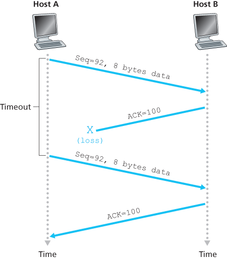
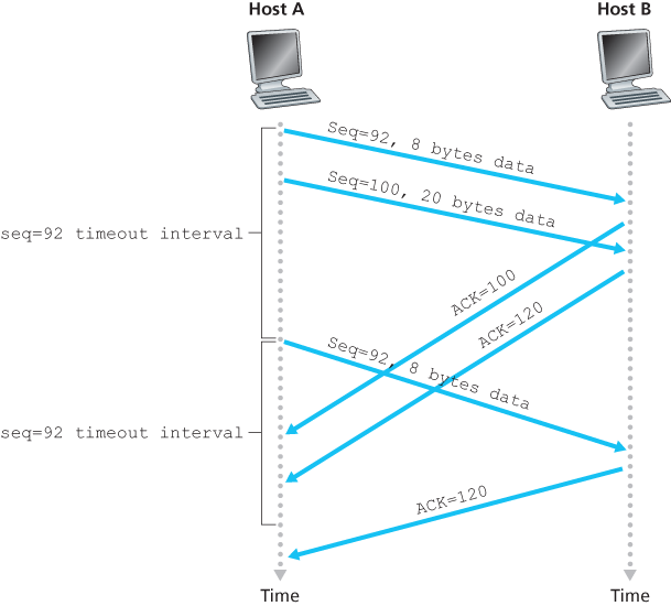
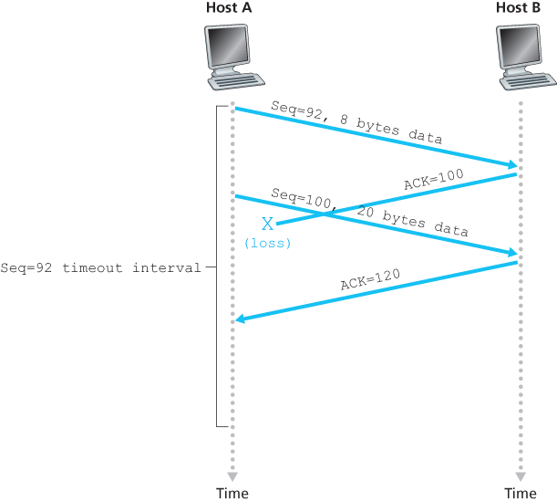
3.5.4 Reliable Data Transfer
The recommended TCP timer management procedures [RFC 6298] use only a single retransmission timer, even if there are multiple transmitted but not yet acknowledged segments.
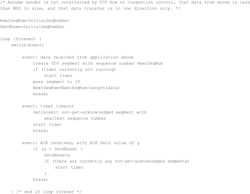
A Few Interesting Scenarios
Doubling the Timeout Interval
A few modifications that most TCP implementations employ. The first concerns the length of the timeout interval after a timer expiration. In this modification, whenever the timeout event occurs, TCP retransmits the not-yet-acknowledged segment with the smallest sequence number, as described above. But each time TCP retransmits, it sets the next timeout interval to twice the previous value, rather than deriving it from the last EstimatedRTT and DevRTT.
Fast Retransmit
The sender can often detect packet loss well before the timeout event occurs by noting so-called duplicate ACKs. A duplicate ACK is an ACK that reacknowledges a segment for which the sender has already received an earlier acknowledgment.
| Event | TCP Receiver Action |
|---|---|
| Arrival of in-order segment with expected sequence number. All data up to expected sequence number already acknowledged. | Delayed ACK. Wait up to 500 msec for arrival of another in-order segment. If next in-order segment does not arrive in this interval, send an ACK. |
| Arrival of in-order segment with expected sequence number. One other in-order segment waiting for ACK transmission. | One Immediately send single cumulative ACK, ACKing both in-order segments. |
| Arrival of out-of-order segment with higher-than-expected sequence number. Gap detected. | Immediately send duplicate ACK, indicating sequence number of next expected byte (which is the lower end of the gap). |
| Arrival of segment that partially or completely fills in gap in received data. | Immediately send ACK, provided that segment starts at the lower end of gap. |
Since TCP does not use negative acknowledgments, the receiver cannot send an explicit negative acknowledgment back to the sender. Instead, it simply reacknowledges (that is, generates a duplicate ACK for) the last in-order byte of data it has received.
Because a sender often sends a large number of segments back to back, if one segment is lost, there will likely be many back-to-back duplicate ACKs. If the TCP sender receives three duplicate ACKs for the same data, it takes this as an indication that the segment following the segment that has been ACKed three times has been lost.
Go-Back-N or Selective Repeat?
TCP looks a lot like a GBN-style protocol. But there are some striking differences between TCP and Go-Back-N. Many TCP implementations will buffer correctly received but out-of-order segments [Stevens 1994].
A proposed modification to TCP, the so-called selective acknowledgment [RFC 2018], allows a TCP receiver to acknowledge out-of-order segments selectively rather than just cumulatively acknowledging the last correctly received, in-order segment. When combined with selective retransmission—skipping the retransmission of segments that have already been selectively acknowledged by the receiver—TCP looks a lot like our generic SR protocol.
3.5.5 Flow Control
TCP provides a flow-control service to its applications to eliminate the possibility of the sender overflowing the receiver’s buffer. Flow control is thus a speed-matching service—matching the rate at which the sender is sending against the rate at which the receiving application is reading.
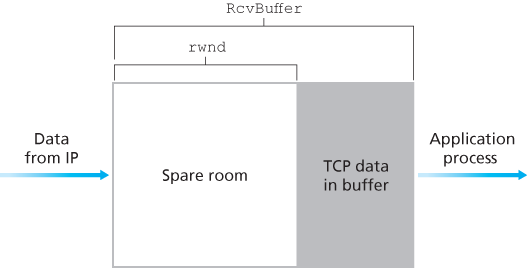
TCP provides flow control by having the sender maintain a variable called the receive window. Informally, the receive window is used to give the sender an idea of how much free buffer space is available at the receiver. Because TCP is full-duplex, the sender at each side of the connection maintains a distinct receive window. Suppose that Host A is sending a large file to Host B over a TCP connection. Host B allocates a receive buffer to this connection; denote its size by RcvBuffer. From time to time, the application process in Host B reads from the buffer. Define the following variables:
LastByteRead: the number of the last byte in the data stream read from the buffer by the application process in BLastByteRcvd: the number of the last byte in the data stream that has arrived from the network and has been placed in the receive buffer at B
The receive window, denoted rwnd is set to the amount of spare room in the buffer:
Host B tells Host A how much spare room it has in the connection buffer by placing its current value of rwnd in the receive window field of every segment it sends to A. Initially, Host B sets rwnd = RcvBuffer. Note that to pull this off, Host B must keep track of several connection-specific variables.
Host A in turn keeps track of two variables, LastByteSent and LastByteAcked, which have obvious meanings. Note that the difference between these two variables, LastByteSent – LastByteAcked, is the amount of unacknowledged data that A has sent into the connection.
Suppose Host B’s receive buffer becomes full so that rwnd = 0. After advertising rwnd = 0 to Host A, also suppose that B has nothing to send to A. Now consider what happens. As the application process at B empties the buffer, TCP does not send new segments with new rwnd values to Host A; indeed, TCP sends a segment to Host A only if it has data to send or if it has an acknowledgment to send. Therefore, Host A is never informed that some space has opened up in Host B’s receive buffer—Host A is blocked and can transmit no more data! To solve this problem, the TCP specification requires Host A to continue to send segments with one data byte when B’s receive window is zero. These segments will be acknowledged by the receiver. Eventually the buffer will begin to empty and the acknowledgments will contain a nonzero rwnd value.
UDP does not provide flow control and consequently, segments may be lost at the receiver due to buffer overflow.
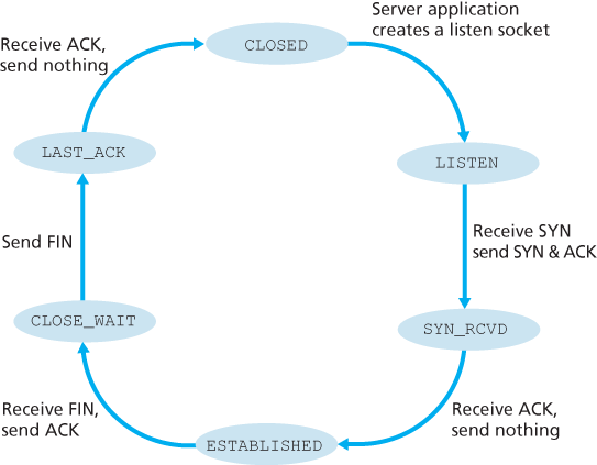
3.5.6 TCP Connection Management
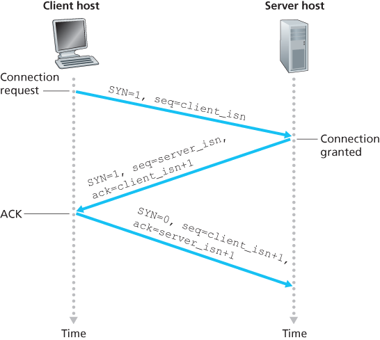
The TCP in the client then proceeds to establish a TCP connection with the TCP in the server in the following manner:
- Step 1. The client-side TCP first sends a special TCP segment to the server-side TCP. This special segment contains no application-layer data. But one of the flag bits in the segment’s header, the SYN bit, is set to 1. For this reason, this special segment is referred to as a SYN segment. In addition, the client randomly chooses an initial sequence number (
client_isn) and puts this number in the sequence number field of the initial TCP SYN segment. This segment is encapsulated within an IP datagram and sent to the server. There has been considerable interest in properly randomizing the choice of theclient_isnin order to avoid certain security attacks [CERT 2001–09]. - Step 2. Once the IP datagram containing the TCP SYN segment arrives at the server host (assuming it does arrive!), the server extracts the TCP SYN segment from the datagram, allocates the TCP buffers and variables to the connection, and sends a connection-granted segment to the client TCP. The allocation of these buffers and variables before completing the third step of the three-way handshake makes TCP vulnerable to a denial-of-service attack known as SYN flooding. This connection-granted segment also contains no application-layer data. However, it does contain three important pieces of information in the segment header. First, the SYN bit is set to 1. Second, the acknowledgment field of the TCP segment header is set to
client_isn+1. Finally, the server chooses its own initial sequence number (server_isn) and puts this value in the sequence number field of the TCP segment header. This connection-granted segment is saying, in effect, “I received your SYN packet to start a connection with your initial sequence number,client_isn. I agree to establish this connection. My own initial sequence number isserver_isn”. The connection-granted segment is referred to as a SYNACK segment. - Step 3. Upon receiving the SYNACK segment, the client also allocates buffers and variables to the connection. The client host then sends the server yet another segment; this last segment acknowledges the server’s connection-granted segment (the client does so by putting the value
server_isn+1in the acknowledgment field of the TCP segment header). The SYN bit is set to zero, since the connection is established. This third stage of the three-way handshake may carry client-to-server data in the segment payload.
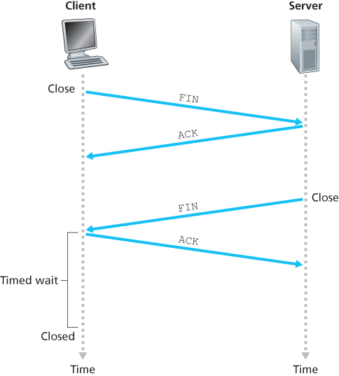
Suppose the client decides to close the connection. The client application process issues a close command. This causes the client TCP to send a special TCP segment to the server process. This special segment has a flag bit in the segment’s header, the FIN bit, set to 1. When the server receives this segment, it sends the client an acknowledgment segment in return. The server then sends its own shutdown segment, which has the FIN bit set to 1. Finally, the client acknowledges the server’s shutdown segment.
During the life of a TCP connection, the TCP protocol running in each host makes transitions through various TCP states.
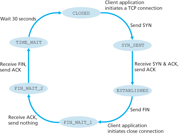
The series of states typically visited by the server-side TCP, assuming the client begins connection teardown.
What happens when a host receives a TCP segment whose port numbers or source IP address do not match with any of the ongoing sockets in the host. For example, suppose a host receives a TCP SYN packet with destination port 80, but the host is not accepting connections on port 80 (that is, it is not running a Web server on port 80). Then the host will send a special reset segment to the source. This TCP segment has the RST flag bit set to 1. When a host receives a UDP packet whose destination port number doesn’t match with an ongoing UDP socket, the host sends a special ICMP datagram.
3.6 Principles of Congestion Control
3.6.2 Approaches to Congestion Control
At the highest level, we can distinguish among congestion-control approaches by whether the network layer provides explicit assistance to the transport layer for congestion-control purposes:
- End-to-end congestion control. In an end-to-end approach to congestion control, the network layer provides no explicit support to the transport layer for congestion-control purposes. Even the presence of network congestion must be inferred by the end systems based only on observed network behavior (for example, packet loss and delay). TCP segment loss (as indicated by a timeout or the receipt of three duplicate acknowledgments) is taken as an indication of network congestion, and TCP decreases its window size accordingly. We’ll also see a more recent proposal for TCP congestion control that uses increasing round-trip segment delay as an indicator of increased network congestion.
- Network-assisted congestion control. With network-assisted congestion control, routers provide explicit feedback to the sender and/or receiver regarding the congestion state of the network. This feedback may be as simple as a single bit indicating congestion at a link – an approach taken in the early IBM SNA [Schwartz 1982], DEC DECnet [Jain 1989; Ramakrishnan 1990] architectures, and ATM [Black 1995] network architectures. More sophisticated feedback is also possible. For example, in ATM Available Bite Rate (ABR) congestion control, a router informs the sender of the maximum host sending rate it (the router) can support on an outgoing link. As noted above, the Internet-default versions of IP and TCP adopt an end-to-end approach towards congestion control.
3.7 TCP Congestion Control
The approach taken by TCP is to have each sender limit the rate at which it sends traffic into its connection as a function of perceived network congestion. If a TCP sender perceives that there is little congestion on the path between itself and the destination, then the TCP sender increases its send rate; if the sender perceives that there is congestion along the path, then the sender reduces its send rate.
The TCP congestion-control mechanism operating at the sender keeps track of an additional variable, the congestion window. The congestion window, denoted cwnd, imposes a constraint on the rate at which a TCP sender can send traffic into the network. Specifically, the amount of unacknowledged data at a sender may not exceed the minimum of cwnd and rwnd, that is:
Roughly, at the beginning of every RTT, the constraint permits the sender to send cwnd bytes of data into the connection; at the end of the RTT the sender receives acknowledgments for the data. Thus the sender’s send rate is roughly cwnd/RTT bytes/sec. By adjusting the value of cwnd, the sender can therefore adjust the rate at which it sends data into its connection.
Note that if acknowledgments arrive at a relatively slow rate (e.g., if the end-end path has high delay or contains a low-bandwidth link), then the congestion window will be increased at a relatively slow rate. On the other hand, if acknowledgments arrive at a high rate, then the congestion window will be increased more quickly. Because TCP uses acknowledgments to trigger (or clock) its increase in congestion window size, TCP is said to be self-clocking.
How then do the TCP senders determine their sending rates such that they don’t congest the network but at the same time make use of all the available bandwidth? Are TCP senders explicitly coordinated, or is there a distributed approach in which the TCP senders can set their sending rates based only on local information? TCP answers these questions using the following guiding principles:
- A lost segment implies congestion, and hence, the TCP sender’s rate should be decreased when a segment is lost. A timeout event or the receipt of four acknowledgments for a given segment (one original ACK and then three duplicate ACKs) is interpreted as an implicit “loss event” indication of the segment following the quadruply ACKed segment, triggering a retransmission of the lost segment. From a congestion-control standpoint, the question is how the TCP sender should decrease its congestion window size, and hence its sending rate, in response to this inferred loss event.
- An acknowledged segment indicates that the network is delivering the sender’s segments to the receiver, and hence, the sender’s rate can be increased when an ACK arrives for a previously unacknowledged segment. The arrival of acknowledgments is taken as an implicit indication that all is well—segments are being successfully delivered from sender to receiver, and the network is thus not congested. The congestion window size can thus be increased.
- Bandwidth probing. Given ACKs indicating a congestion-free source-to-destination path and loss events indicating a congested path, TCP’s strategy for adjusting its transmission rate is to increase its rate in response to arriving ACKs until a loss event occurs, at which point, the transmission rate is decreased. The TCP sender thus increases its transmission rate to probe for the rate that at which congestion onset begins, backs off from that rate, and then to begins probing again to see if the congestion onset rate has changed. The TCP sender’s behavior is perhaps analogous to the child who requests (and gets) more and more goodies until finally he/she is finally told “No!”, backs off a bit, but then begins making requests again shortly afterwards. Note that there is no explicit signaling of congestion state by the network—ACKs and loss events serve as implicit signals—and that each TCP sender acts on local information asynchronously from other TCP senders.
TCP congestion-control algorithm, which was first described in [Jacobson 1988] and is standardized in [RFC 5681]. The algorithm has three major components: (1) slow start, (2) congestion avoidance, and (3) fast recovery. Slow start and congestion avoidance are mandatory components of TCP, differing in how they increase the size of cwnd in response to received ACKs. Fast recovery is recommended, but not required, for TCP senders.
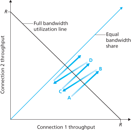
3.7.1 Fairness
Consider K TCP connections, each with a different end-to-end path, but all passing through a bottleneck link with transmission rate R bps. A congestion-control mechanism is said to be fair if the average transmission rate of each connection is approximately R/K; that is, each connection gets an equal share of the link bandwidth.
Fairness and UDP
Because TCP congestion control will decrease its transmission rate in the face of increasing congestion (loss), while UDP sources need not, it is possible for UDP sources to crowd out TCP traffic.
Fairness and Parallel TCP Connections
When an application uses multiple parallel connections, it gets a larger fraction of the bandwidth in a congested link.