
Chapter 1 Computer Networks and the Internet
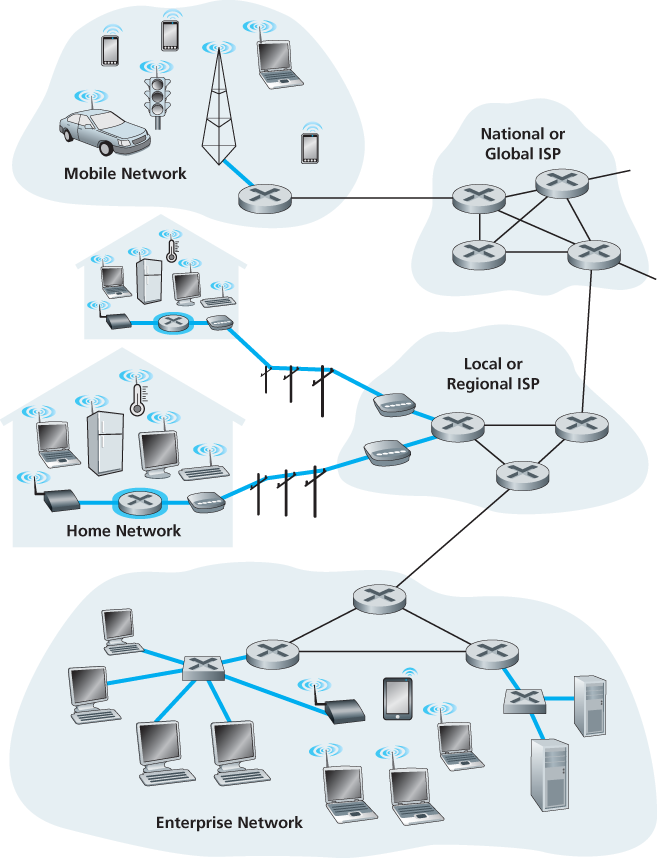
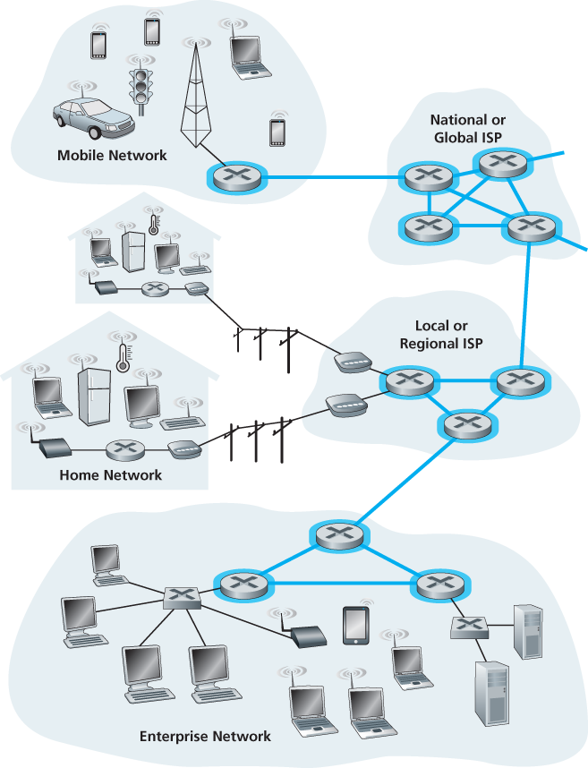
The Internet is a network of networks.
1.1 What Is the Internet?
1.1.1 A Nuts-and-Bolts Description
The Internet is a computer network that interconnects billions of computing devices throughout the world.
The term computer network is beginning to sound a bit dated, given the many nontraditional devices that are being hooked up to the Internet. In Internet jargon, all of these devices are called hosts or end systems.
End systems are connected together by a network of communication links and packet switches. There are many types of communication links, which are made up of different types of physical media, including coaxial cable, copper wire, optical fiber, and radio spectrum. Different links can transmit data at different rates, with the transmission rate of a link measured in bits/second. When one end system has data to send to another end system, the sending end system segments the data and adds header bytes to each segment. The resulting packages of information, known as packets in the jargon of computer networks, are then sent through the network to the destination end system, where they are reassembled into the original data.
A packet switch takes a packet arriving on one of its incoming communication links and forwards that packet on one of its outgoing communication links. Packet switches come in many shapes and flavors, but the two most prominent types in today’s Internet are routers and link-layer switches. Both types of switches forward packets toward their ultimate destinations. Link-layer switches are typically used in access networks, while routers are typically used in the network core. The sequence of communication links and packet switches traversed by a packet from the sending end system to the receiving end system is known as a route or path through the network.
End systems access the Internet through Internet Service Providers (ISPs).
Each ISP network, whether upper-tier or lower-tier, is managed independently, runs the IP protocol (see below), and conforms to certain naming and address conventions.
End systems, packet switches, and other pieces of the Internet run protocols that control the sending and receiving of information within the Internet. The Transmission Control Protocol (TCP) and the Internet Protocol (IP) are two of the most important protocols in the Internet. The IP protocol specifies the format of the packets that are sent and received among routers and end systems. The Internet’s principal protocols are collectively known as TCP/IP.
Internet standards are developed by the Internet Engineering Task Force (IETF). The IETF standards documents are called requests for comments (RFCs).
1.1.2 A Services Description
End systems attached to the Internet provide a socket interface that specifies how a program running on one end system asks the Internet infrastructure to deliver data to a specific destination program running on another end system. This Internet socket interface is a set of rules that the sending program must follow so that the Internet can deliver the data to the destination program.
1.1.3 What Is a Protocol?
Network Protocols
A protocol defines the format and the order of messages exchanged between two or more communicating entities, as well as the actions taken on the transmission and/or receipt of a message or other event.
1.2 The Network Edge
1.2.1 Access Networks
The network that physically connects an end system to the first router (also known as the “edge router”) on a path from the end system to any other distant end system.
Home Access: DSL, Cable, FTTH, Dial-Up, and Satellite
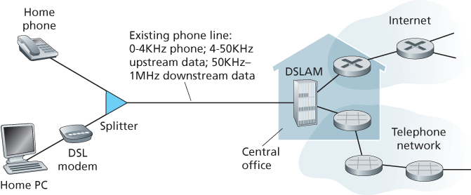
Today, the two most prevalent types of broadband residential access are digital subscriber line (DSL) and cable. A residence typically obtains DSL Internet access from the same local telephone company (telco) that provides its wired local phone access. each customer’s DSL modem uses the existing telephone line (twisted-pair copper wire) to exchange data with a digital subscriber line access multiplexer (DSLAM) located in the telco’s local central office (CO). The home’s DSL modem takes digital data and translates it to high-frequency tones for transmission over telephone wires to the CO; the analog signals from many such houses are translated back into digital format at the DSLAM.
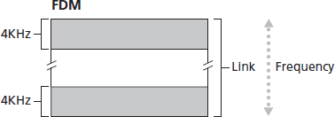
The residential telephone line carries both data and traditional telephone signals simultaneously, which are encoded at different frequencies:
- A high-speed downstream channel, in the 50 kHz to 1 MHz band
- A medium-speed upstream channel, in the 4 kHz to 50 kHz band
- An ordinary two-way telephone channel, in the 0 to 4 kHz band
This approach makes the single DSL link appear as if there were three separate links, so that a telephone call and an Internet connection can share the DSL link at the same time.
The DSL standards define multiple transmission rates, including 12 Mbps downstream and 1.8 Mbps upstream [ITU 1999], and 55 Mbps downstream and 15 Mbps upstream [ITU 2006]. Because the downstream and upstream rates are different, the access is said to be asymmetric.
While DSL makes use of the telco’s existing local telephone infrastructure, cable Internet access makes use of the cable television company’s existing cable television infrastructure. A residence obtains cable Internet access from the same company that provides its cable television. Because both fiber and coaxial cable are employed in this system, it is often referred to as hybrid fiber coax (HFC).
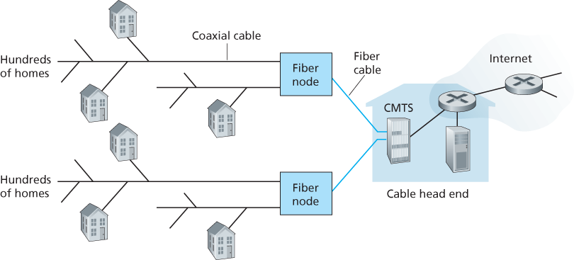
Cable internet access requires special modems, called cable modems. As with a DSL modem, the cable modem is typically an external device and connects to the home PC through an Ethernet port. At the cable head end, the cable modem termination system (CMTS) serves a similar function as the DSL network’s DSLAM—turning the analog signal sent from the cable modems in many downstream homes back into digital format. Cable modems divide the HFC network into two channels, a downstream and an upstream channel. As with DSL, access is typically asymmetric, with the downstream channel typically allocated a higher transmission rate than the upstream channel. The DOCSIS 2.0 standard defines downstream rates up to 42.8 Mbps and upstream rates of up to 30.7 Mbps.
One important characteristic of cable Internet access is that it is a shared broadcast medium. In particular, every packet sent by the head end travels downstream on every link to every home and every packet sent by a home travels on the upstream channel to the head end. Because the upstream channel is also shared, a distributed multiple access protocol is needed to coordinate transmissions and avoid collisions.
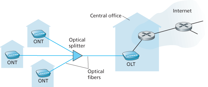
An up-and-coming technology that provides even higher speeds is fiber to the home (FTTH) [FTTH Council 2016]. As the name suggests, the FTTH concept is simple—provide an optical fiber path from the CO directly to the home.
There are several competing technologies for optical distribution from the CO to the homes. The simplest optical distribution network is called direct fiber, with one fiber leaving the CO for each home. More commonly, each fiber leaving the central office is actually shared by many homes; it is not until the fiber gets relatively close to the homes that it is split into individual customer-specific fibers. There are two competing optical-distribution network architectures that perform this splitting: active optical networks (AONs) and passive optical networks (PONs). AON is essentially switched Ethernet.
The PON distribution architecture:
Two other access network technologies are also used to provide Internet access to the home. In locations where DSL, cable, and FTTH are not available (e.g., in some rural settings), a satellite link can be used to connect a residence to the Internet at speeds of more than 1 Mbps; StarBand and HughesNet are two such satellite access providers. Dial-up access over traditional phone lines is based on the same model as DSL—a home modem connects over a phone line to a modem in the ISP. Compared with DSL and other broadband access networks, dial-up access is excruciatingly slow at 56 kbps.
Access in the Enterprise (and the Home): Ethernet and WiFi
On corporate and university campuses, and increasingly in home settings, a local area network (LAN) is used to connect an end system to the edge router. Although there are many types of LAN technologies, Ethernet is by far the most prevalent access technology in corporate, university, and home networks.
A wireless LAN user must typically be within a few tens of meters of the access point. Wireless LAN access based on IEEE 802.11 technology, more colloquially known as WiFi.
1.2.2 Physical Media
Physical media fall into two categories: guided media and unguided media. With guided media, the waves are guided along a solid medium, such as a fiber-optic cable, a twisted-pair copper wire, or a coaxial cable. With unguided media, the waves propagate in the atmosphere and in outer space, such as in a wireless LAN or a digital satellite channel.
Twisted-Pair Copper Wire
Twisted pair consists of two insulated copper wires, each about 1 mm thick, arranged in a regular spiral pattern. The wires are twisted together to reduce the electrical interference from similar pairs close by. Typically, a number of pairs are bundled together in a cable by wrapping the pairs in a protective shield. A wire pair constitutes a single communication link. Unshielded twisted pair (UTP) is commonly used for computer networks within a building, that is, for LANs. Data rates for LANs using twisted pair today range from 10 Mbps to 10 Gbps. The data rates that can be achieved depend on the thickness of the wire and the distance between transmitter and receiver.
Modern twisted-pair technology, such as category 6a cable, can achieve data rates of 10 Gbps for distances up to a hundred meters.
Coaxial Cable
Coaxial cable consists of two copper conductors, but the two conductors are concentric rather than parallel. With this construction and special insulation and shielding, coaxial cable can achieve high data transmission rates.
Fiber Optics
An optical fiber is a thin, flexible medium that conducts pulses of light, with each pulse representing a bit. A single optical fiber can support tremendous bit rates, up to tens or even hundreds of gigabits per second. They are immune to electromagnetic interference, have very low signal attenuation up to 100 kilometers, and are very hard to tap. The Optical Carrier (OC) standard link speeds range from 51.8 Mbps to 39.8 Gbps; these specifications are often referred to as OC-n, where the link speed equals n ∞ 51.8 Mbps. Standards in use today include OC-1, OC-3, OC-12, OC-24, OC-48, OC-96, OC-192, OC-768. [Mukherjee 2006, Ramaswami 2010] provide coverage of various aspects of optical networking.
Terrestrial Radio Channels
Radio channels carry signals in the electromagnetic spectrum. They are an attractive medium because they require no physical wire to be installed, can penetrate walls, provide connectivity to a mobile user, and can potentially carry a signal for long distances. The characteristics of a radio channel depend significantly on the propagation environment and the distance over which a signal is to be carried. Environmental considerations determine path loss and shadow fading (which decrease the signal strength as the signal travels over a distance and around/through obstructing objects), multipath fading (due to signal reflection off of interfering objects), and interference (due to other transmissions and electromagnetic signals).
Satellite Radio Channels
A communication satellite links two or more Earth-based microwave transmitter/ receivers, known as ground stations. The satellite receives transmissions on one frequency band, regenerates the signal using a repeater (discussed below), and transmits the signal on another frequency. Two types of satellites are used in communications: geostationary satellites and low-earth orbiting (LEO) satellites [Wiki Satellite 2016].
Geostationary satellites permanently remain above the same spot on Earth. This stationary presence is achieved by placing the satellite in orbit at 36,000 kilometers above Earth’s surface. This huge distance from ground station through satellite back to ground station introduces a substantial signal propagation delay of 280 milliseconds.
LEO satellites are placed much closer to Earth and do not remain permanently above one spot on Earth. They rotate around Earth (just as the Moon does) and may communicate with each other, as well as with ground stations. To provide continuous coverage to an area, many satellites need to be placed in orbit. There are currently many low-altitude communication systems in development. LEO satellite technology may be used for Internet access sometime in the future.
1.3 The Network Core
1.3.1 Packet Switching
To send a message from a source end system to a destination end system, the source breaks long messages into smaller chunks of data known as packets. Between source and destination, each packet travels through communication links and packet switches (for which there are two predominant types, routers and link-layer switches).
Store-and-Forward Transmission
Most packet switches use store-and-forward transmission at the inputs to the links. Store-and-forward transmission means that the packet switch must receive the entire packet before it can begin to transmit the first bit of the packet onto the outbound link.
Queuing Delays and Packet Loss
Each packet switch has multiple links attached to it. For each attached link, the packet switch has an output buffer (also called an output queue), which stores packets that the router is about to send into that link. The output buffers play a key role in packet switching. If an arriving packet needs to be transmitted onto a link but finds the link busy with the transmission of another packet, the arriving packet must wait in the output buffer. Thus, in addition to the store-and-forward delays, packets suffer output buffer queuing delays. These delays are variable and depend on the level of congestion in the network. Since the amount of buffer space is finite, an arriving packet may find that the buffer is completely full with other packets waiting for transmission. In this case, packet loss will occur—either the arriving packet or one of the already-queued packets will be dropped.
Forwarding Tables and Routing Protocols
Packet forwarding is actually done in different ways in different types of computer networks.
In the Internet, every end system has an address called an IP address. When a source end system wants to send a packet to a destination end system, the source includes the destination’s IP address in the packet’s header. As with postal addresses, this address has a hierarchical structure. When a packet arrives at a router in the network, the router examines a portion of the packet’s destination address and forwards the packet to an adjacent router. More specifically, each router has a forwarding table that maps destination addresses (or portions of the destination addresses) to that router’s outbound links. When a packet arrives at a router, the router examines the address and searches its forwarding table, using this destination address, to find the appropriate outbound link. The router then directs the packet to this outbound link.
The Internet has a number of special routing protocols that are used to automatically set the forwarding tables. A routing protocol may, for example, determine the shortest path from each router to each destination and use the shortest path results to configure the forwarding tables in the routers.
1.3.2 Circuit Switching
There are two fundamental approaches to moving data through a network of links and switches: circuit switching and packet switching.
In circuit-switched networks, the resources needed along a path (buffers, link transmission rate) to provide for communication between the end systems are reserved for the duration of the communication session between the end systems. In packet-switched networks, these resources are not reserved; a session’s messages use the resources on demand and, as a consequence, may have to wait (that is, queue) for access to a communication link.
Multiplexing in Circuit-Switched Networks
A circuit in a link is implemented with either frequency-division multiplexing (FDM) or time-division multiplexing (TDM). With FDM, the frequency spectrum of a link is divided up among the connections established across the link. Specifically, the link dedicates a frequency band to each connection for the duration of the connection. In telephone networks, this frequency band typically has a width of 4 kHz (that is, 4,000 hertz or 4,000 cycles per second). The width of the band is called, not surprisingly, the bandwidth. FM radio stations also use FDM to share the frequency spectrum between 88 MHz and 108 MHz, with each station being allocated a specific frequency band.
For a TDM link, time is divided into frames of fixed duration, and each frame is divided into a fixed number of time slots. When the network establishes a connection across a link, the network dedicates one time slot in every frame to this connection. These slots are dedicated for the sole use of that connection, with one time slot available for use (in every frame) to transmit the connection’s data.
1.4 Delay, Loss, and Throughput in Packet-Switched Networks
1.4.1 Overview of Delay in Packet-Switched Networks
Types of Delay
Processing Delay
The time required to examine the packet’s header and determine where to direct the packet is part of the processing delay. The processing delay can also include other factors, such as the time needed to check for bit-level errors in the packet that occurred in transmitting the packet’s bits from the upstream node to router A.
Queuing Delay
At the queue, the packet experiences a queuing delay as it waits to be transmitted onto the link. The length of the queuing delay of a specific packet will depend on the number of earlier-arriving packets that are queued and waiting for transmission onto the link. If the queue is empty and no other packet is currently being transmitted, then our packet’s queuing delay will be zero.
Transmission Delay
This is the amount of time required to push (that is, transmit) all of the packet’s bits into the link.
Propagation Delay
The propagation speed depends on the physical medium of the link (that is, fiber optics, twisted-pair copper wire, and so on) and is in the range of which is equal to, or a little less than, the speed of light. The propagation delay is the distance between two routers divided by the propagation speed.
Comparing Transmission and Propagation Delay
The transmission delay is the amount of time required for the router to push out the packet; it is a function of the packet’s length and the transmission rate of the link, but has nothing to do with the distance between the two routers. The propagation delay, on the other hand, is the time it takes a bit to propagate from one router to the next; it is a function of the distance between the two routers, but has nothing to do with the packet’s length or the transmission rate of the link.
1.4.2 Queuing Delay and Packet Loss
Packet Loss
A packet can arrive to find a full queue. With no place to store such a packet, a router will drop that packet; that is, the packet will be lost.
1.4.3 End-to-End Delay
Traceroute
Traceroute is a simple program that can run in any Internet host. When the user specifies a destination hostname, the program in the source host sends multiple, special packets toward that destination. As these packets work their way toward the destination, they pass through a series of routers. When a router receives one of these special packets, it sends back to the source a short message that contains the name and address of the router.
More specifically, suppose there are
1.4.4 Throughput in Computer Networks
To define throughput, consider transferring a large file from Host A to Host B across a computer network. The instantaneous throughput at any instant of time is the rate (in bits/sec) at which Host B is receiving the file. If the file consists of F bits and the transfer takes T seconds for Host B to receive all F bits, then the average throughput of the file transfer is F/T bits/sec.
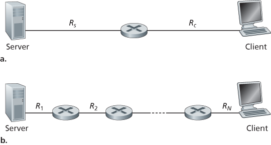
The throughput is min{Rc, Rs}, that is, it is the transmission rate of the bottleneck link.
1.5 Protocol Layers and Their Service Models
1.5.1 Layered Architecture
Protocol Layering
To provide structure to the design of network protocols, network designers organize protocols—and the network hardware and software that implement the protocols—in layers. We are again interested in the services that a layer offers to the layer above—the so-called service model of a layer. Each layer provides its service by (1) performing certain actions within that layer and by (2) using the services of the layer directly below it.
One potential drawback of layering is that one layer may duplicate lower-layer functionality. For example, many protocol stacks provide error recovery on both a per-link basis and an end-to-end basis. A second potential drawback is that functionality at one layer may need information (for example, a timestamp value) that is present only in another layer; this violates the goal of separation of layers.
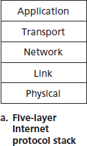
When taken together, the protocols of the various layers are called the protocol stack. The Internet protocol stack consists of five layers: the physical, link, network, transport, and application layers.
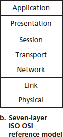
The OSI Model
Back in the late 1970s, the International Organization for Standardization (ISO) proposed that computer networks be organized around seven layers, called the Open Systems Interconnection (OSI) model [ISO 2016].
The seven layers of the OSI reference model are: application layer, presentation layer, session layer, transport layer, network layer, data link layer, and physical layer.
1.5.2 Encapsulation
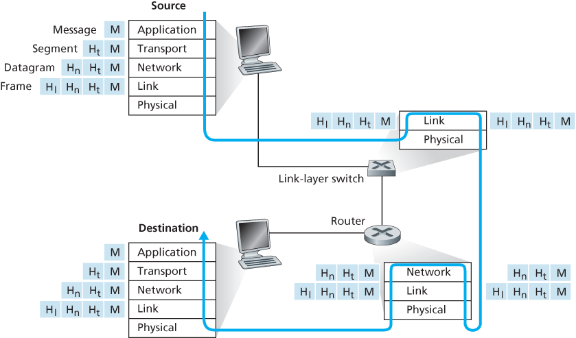
Routers and link-layer switches are both packet switches. Similar to end systems, routers and link-layer switches organize their networking hardware and software into layers. But routers and link-layer switches do not implement all of the layers in the protocol stack; they typically implement only the bottom layers. Link-layer switches implement layers 1 and 2; routers implement layers 1 through 3. This means, for example, that Internet routers are capable of implementing the IP protocol (a layer 3 protocol), while link-layer switches are not. We’ll see later that while link-layer switches do not recognize IP addresses, they are capable of recognizing layer 2 addresses, such as Ethernet addresses.
At the sending host, an application-layer message is passed to the transport layer. In the simplest case, the transport layer takes the message and appends additional information that will be used by the receiver-side transport layer. The application-layer message and the transport-layer header information together constitute the transport-layer segment. The transport-layer segment thus encapsulates the application-layer message. The added information might include information allowing the receiver-side transport layer to deliver the message up to the appropriate application, and error-detection bits that allow the receiver to determine whether bits in the message have been changed in route. The transport layer then passes the segment to the network layer, which adds network-layer header information such as source and destination end system addresses, creating a network-layer datagram. The datagram is then passed to the link layer, which (of course!) will add its own link-layer header information and create a link-layer frame. Thus, we see that at each layer, a packet has two types of fields: header fields and a payload field. The payload is typically a packet from the layer above.